
Device and method for controlling robot

一种控制装置、机械手的技术,应用在机械手、计算机控制、程序控制机械手等方向,能够解决机械手的作业程序相关性受损等问题

Active Publication Date: 2006-12-13
FANUC LTD
View PDF1 Cites 24 Cited by
  • Summary
  • Abstract
  • Description
  • Claims
  • Application Information

AI Technical Summary

Problems solved by technology

If the operator manually intervenes in the system, the state of the production system changes from the state at the time of emergency stop, and the correlation with the work program of the robot is lost, so the work cannot be restarted without change.

Method used


Image

  • Device and method for controlling robot
  • Device and method for controlling robot
  • Device and method for controlling robot

Examples


Embodiment Construction

[0036] Embodiments of the present invention will be described in detail below with reference to the drawings. In the drawings, the same or similar structural elements are given common reference signs.

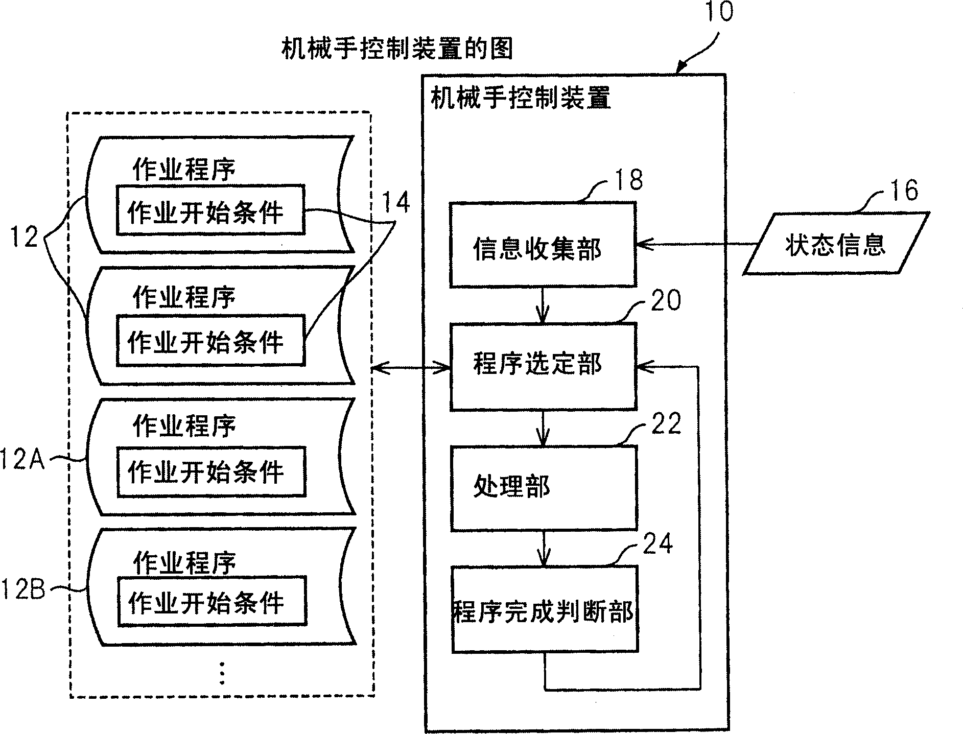
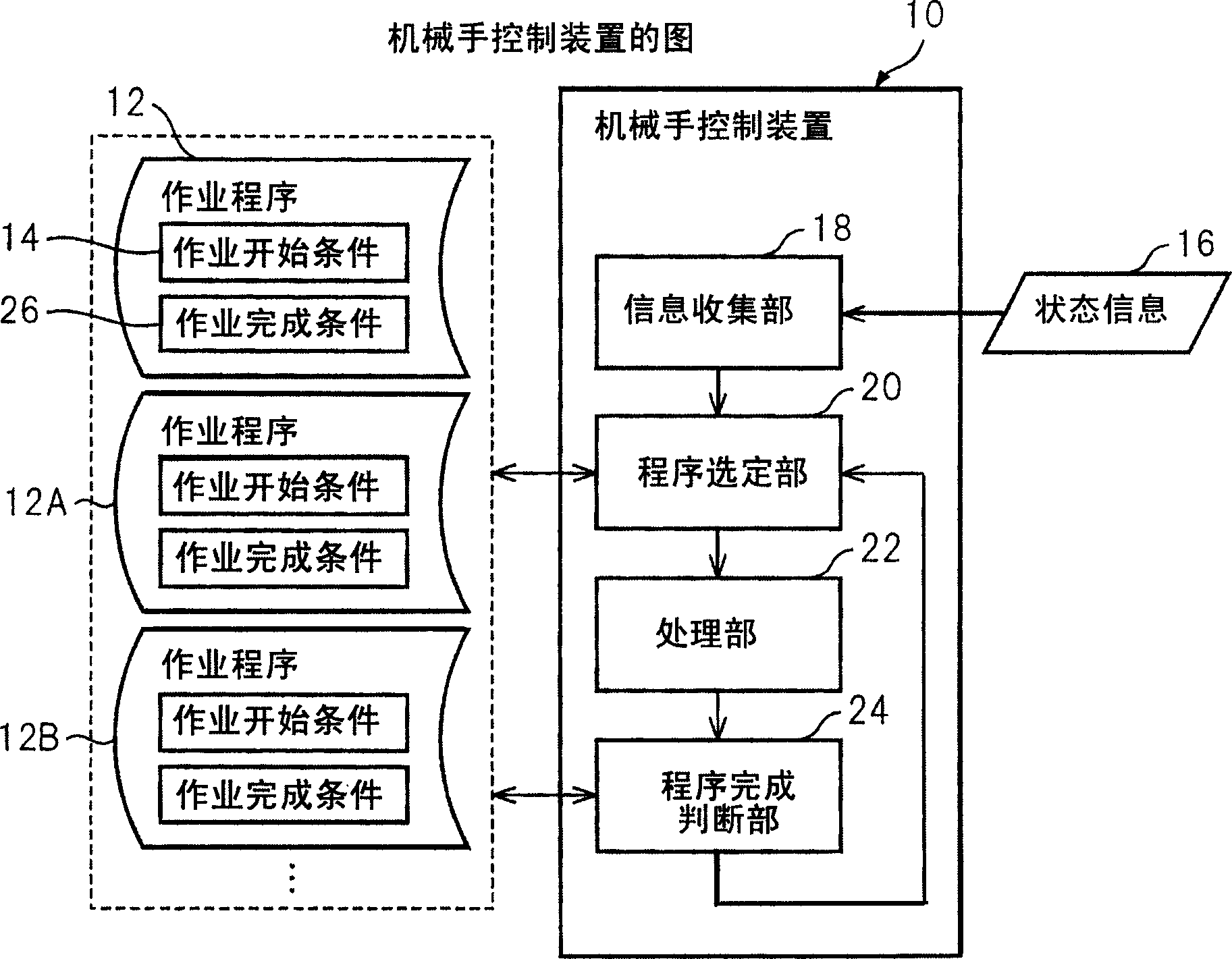
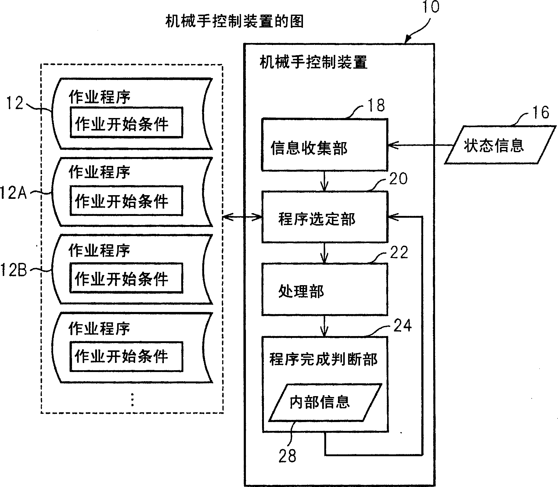
[0037] With reference to the accompanying drawings, figure 1 The basic structure of the robot control device 10 of the present invention is shown in a functional block diagram. The robot control device 10 causes the manipulator to execute operations including a plurality of work units in parallel with respect to a plurality of workpieces in accordance with a plurality of work programs 12 that respectively instruct a plurality of work units. Here, each of the plurality of work programs 12 includes descriptions of work start conditions on the premise that the robot starts the corresponding work unit. The manipulator control device 10 has an information collection unit 18 that collects state information 16 that indicates the state of the environment in which the manipulator perf...


PUM


Abstract

The robot controller includes an information collecting section collecting state information showing, in real time, a state of an environment of the robot; a program selecting section selecting a first executable program satisfying a task starting condition, from operation programs ready to be executed for workpieces, based on the state information; a processing section processing, for execution, the first executable program; and a program-completion judging section judging whether the processing section has completed a processing of the first executable program. The program selecting section selects, based on the state information, a second executable program satisfying the task starting condition, from the operation programs ready to be executed, so as to satisfy a judgment of the program-completion judging section.

Description

technical field [0001] The invention relates to a control device and a control method of an industrial manipulator. Background technique [0002] Industrial manipulators (hereinafter referred to as robots) operate in accordance with specific operating procedures (ie, task procedures). By appropriately selecting various types of work programs corresponding to the type of tool (that is, the end effector) installed on the manipulator, the type of workpiece to be worked on, and the content of the work, and giving it to the manipulator, a variety of tasks can be performed by one manipulator. Operation. When making a work program to move the manipulator, the teaching operation panel is generally used. The operator manually moves each control axis of the manipulator at a low speed, sequentially positions the tool on multiple work parts that perform work on the workpiece, and performs these tasks The parts are stored in the robot as "teach points". The manipulator stores, as info...

Claims


Application Information

Patent Timeline
Patent Type & Authority Applications(China)
IPC IPC(8): B25J13/00B25J9/16G05B19/4067G05B19/4155
CPCB25J9/1656G05B2219/40584B25J9/1679
Inventor 二瓶亮加藤哲朗西浩次
Owner FANUC LTD
Learn More