Cable work well and construction method thereof

A construction method and technology for working wells, applied in artificial islands, water conservancy projects, infrastructure engineering, etc., can solve problems such as high requirements for lifting equipment, high lifting difficulty, and limited choice of working well shapes

Inactive Publication Date: 2006-12-13
SHANGHAI JIULONG ELECTRIC POWER GROUP
View PDF0 Cites 3 Cited by
  • Summary
  • Abstract
  • Description
  • Claims
  • Application Information

AI Technical Summary

Problems solved by technology

Its disadvantages are: high requirements for lifting equipment required for construction, high lifting difficulty, and small choice of working well shape.

Method used


Image

  • Cable work well and construction method thereof
  • Cable work well and construction method thereof

Examples


Embodiment Construction

[0022] The present invention will be further described below with reference to the accompanying drawings and embodiments.

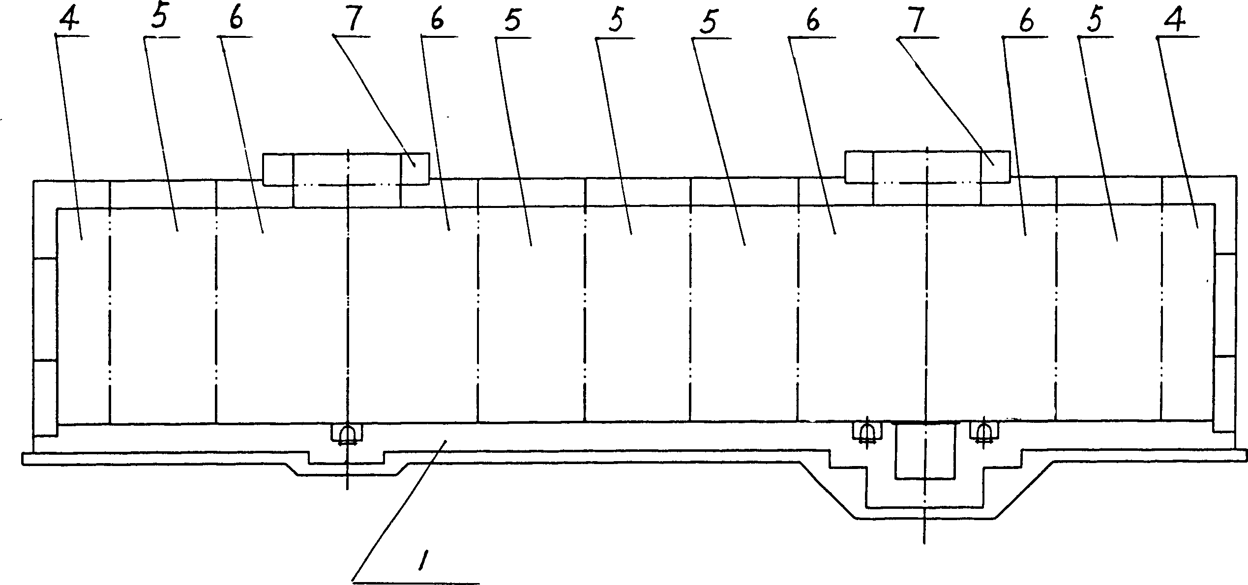
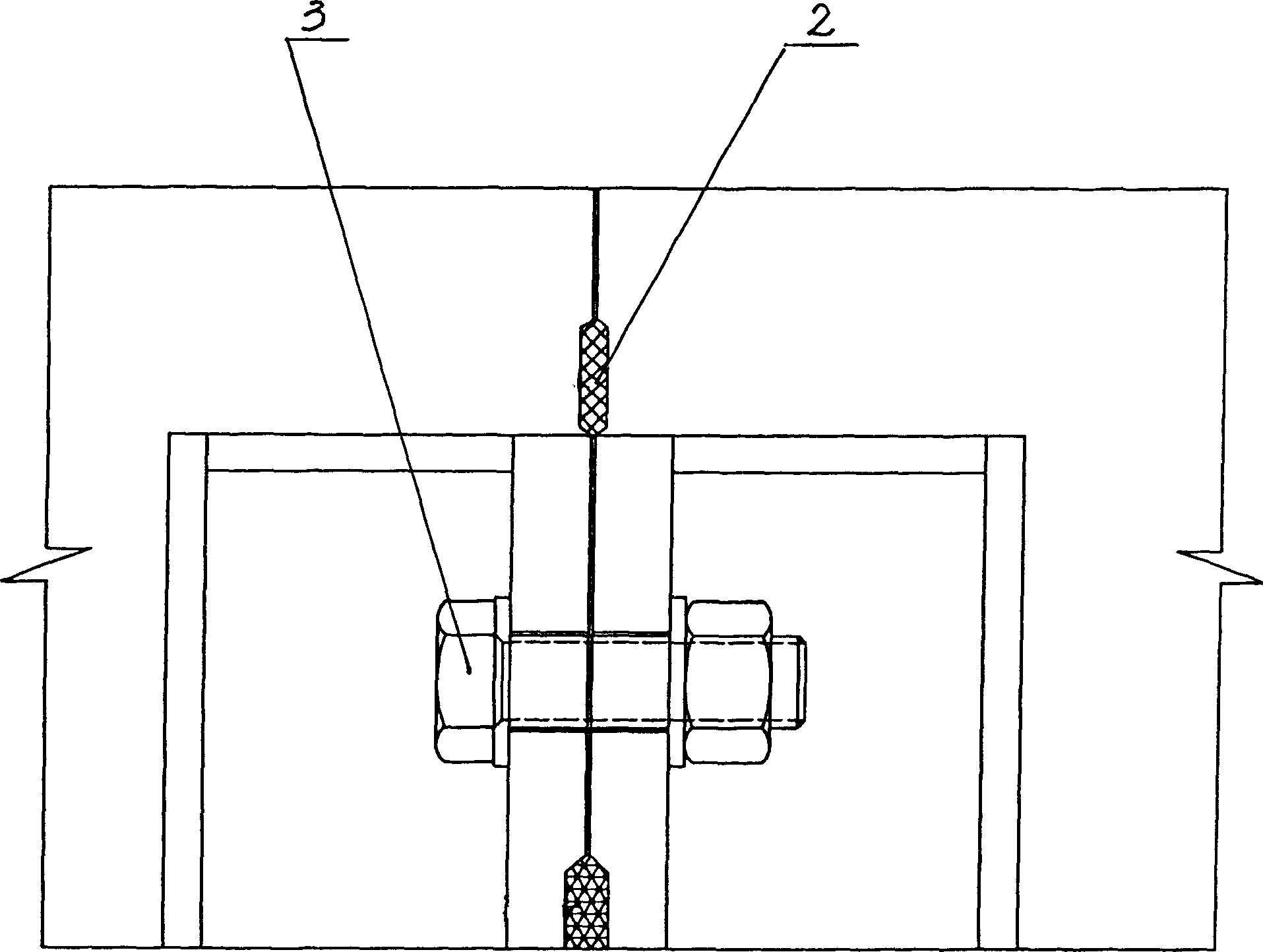
[0023] like figure 1 , 2 As shown, the cable work well includes a base 1, a well body, a seal 2 and a bolt group 3. The base 1 is a cast-in-place reinforced concrete base, and the well body consists of two D-type blocks 4 and five B-type blocks 5. , four TD blocks 6 and two TK blocks 7, a total of thirteen prefabricated building blocks. like figure 2 As shown, the joints between the prefabricated building blocks are cushioned with seals, and the prefabricated building blocks are connected by bolt groups. There is also a seal at the seam between the prefabricated member and the base.

[0024] This embodiment is constructed according to the following steps and methods:

[0025] i. Construction of foundation pit enclosure for cable work wells;

[0026] ii. Foundation pit excavation;

[0027] iii. C10 plain concrete cushion pouring;

[0028] iv. Rein...


PUM


Abstract

The invention relates to a cable working well and relative construction, which is characterized in that: the base is formed by steel bar concrete on-site pouring method; the well body is formed by several preformed blocks; since it uses preformed assembly method and steel bar concrete on-site pouring method, it can overcome the defects as low strength, low speed, easy leakage, etc of present technique as brick working well, on-site concrete working well, etc.

Description

technical field [0001] The invention relates to underground pipeline well technology, in particular to a cable working well and a construction method thereof. Background technique [0002] The existing cable working wells have the following forms: working wells made of clay bricks, cast-in-place concrete working wells, concrete block working wells and prefabricated assembled working wells. [0003] The cable work wells made of clay bricks have low strength, slow construction, easy leakage and poor durability, and have been gradually replaced by cast-in-place concrete work wells. [0004] Reinforced concrete working wells are the most commonly used solutions in current projects. However, the cast-in-situ method of reinforced concrete has a long construction period, it is difficult to effectively control the project cost, and it is difficult to reliably guarantee the project quality. The small plate steel mold commonly used in the cast-in-place molding of reinforced concrete...

Claims


Application Information

Patent Timeline
Patent Type & Authority Applications(China)
IPC IPC(8): E02D29/12
Inventor 曹雪峰
Owner SHANGHAI JIULONG ELECTRIC POWER GROUP
Why Eureka
Try Eureka