
Internal combustion engine

An internal combustion engine and cylinder technology, which is applied in mechanical equipment, engine components, machines/engines, etc., can solve the problems of complex internal combustion engine structure and achieve the effect of compact structure

Inactive Publication Date: 2006-12-13
MAN ENERGY SOLUTIONS SE
View PDF0 Cites 3 Cited by
  • Summary
  • Abstract
  • Description
  • Claims
  • Application Information

AI Technical Summary

Problems solved by technology

This makes the structure of the internal combustion engine complex

Method used


Image

  • Internal combustion engine
  • Internal combustion engine
  • Internal combustion engine

Examples


Embodiment Construction

[0017] Below with the help of Figure 1 to Figure 10 The present invention is described in detail.

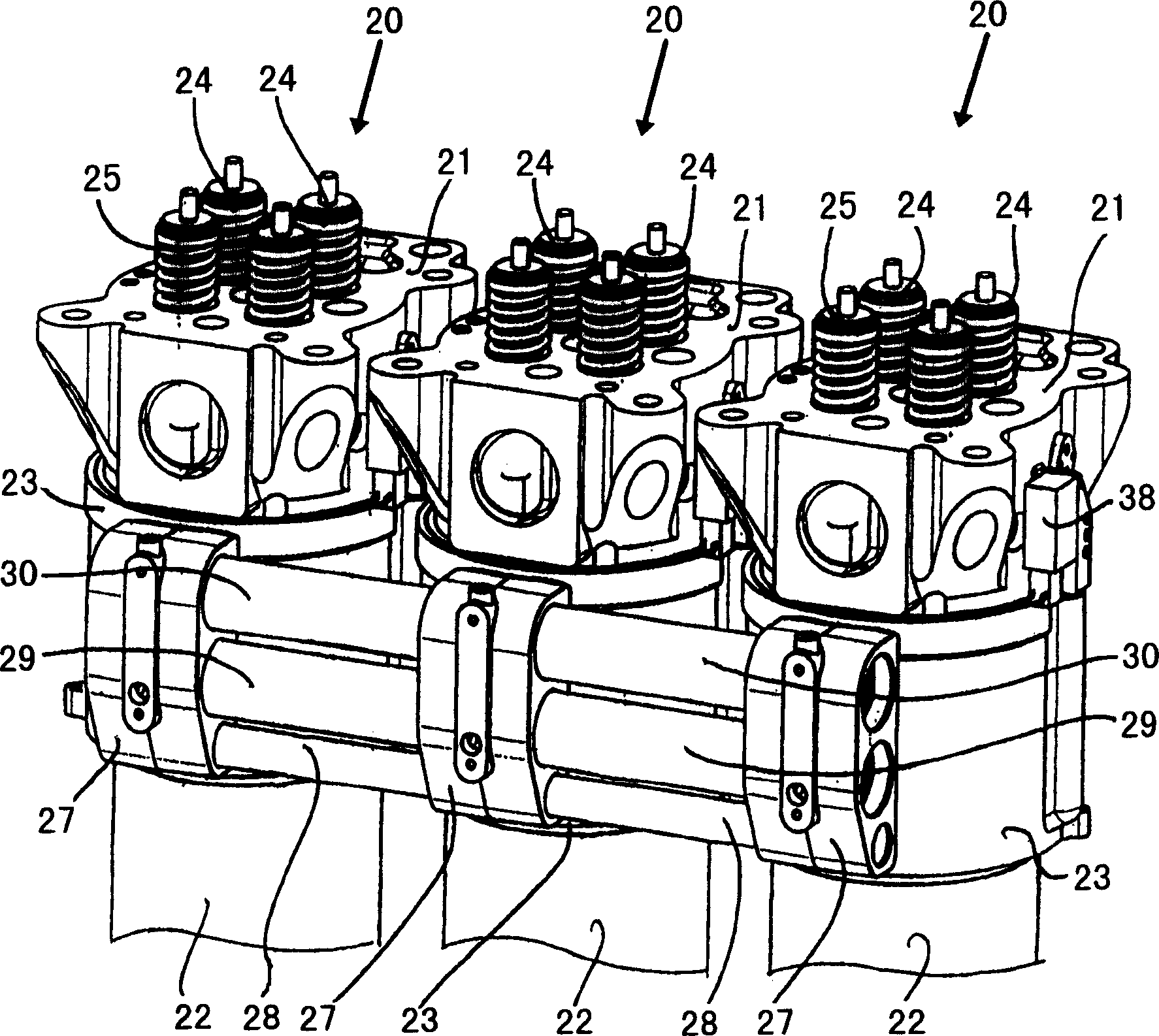
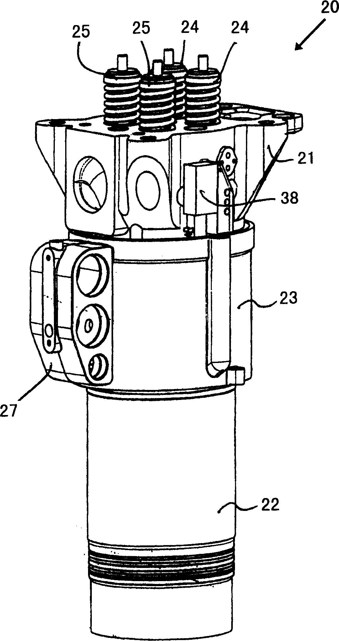
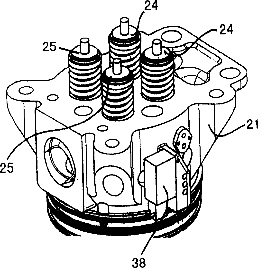
[0018] figure 1 Partially shows the area of ​​three cylinder units arranged in a row in an internal combustion engine according to the invention, wherein each cylinder unit 20 comprises a cylinder head 21, a cylinder liner 22 and a duct arrangement 23 for cooling water and starting air . In the exemplary embodiment shown, two intake valves 24 for combustion air and two exhaust valves for exhaust gases are combined in the cylinder head 21 of each cylinder unit 20 . In the area between the intake valve 24 and the exhaust valve 25, the opening 26 combined in the cylinder head 21 (see Image 6 ) is integrated into the cylinder unit 20 for fuel, not shown. The pipe arrangement 23 for cooling water and starting air of each cylinder unit 20 surrounds the cylinder head 21 and the cylinder liner 22 of the respective cylinder unit 20 in a section at which the cylinder head 21 and the...


PUM


Abstract

The invention relates to an internal combustion engine having a plurality of cylinder units (20), wherein each cylinder unit (20) has a cylinder head (21) and a cylinder liner (22). According to the present invention each cylinder unit (20) also comprises a cooling water and starting air duct arrangement (23), wherein the cooling water and starting air duct arrangement (23) surrounds the cylinder head (21) and the cylinder head (21) and Cylinder liner (22), connecting the cylinder head (21) and cylinder liner (22) on this section, and wherein said cooling water and starting air piping device (23) and cylinder head (21) and cylinder liner (22 ) delimit a channel section of a starting air inlet channel, a channel section of a cooling water inlet channel and a channel section of a cooling water outlet channel for each cylinder unit.

Description

technical field [0001] The invention relates to an internal combustion engine. Background technique [0002] Internal combustion engines, such as large diesel engines used on ships, have a number of cylinder units, each cylinder unit having a cylinder head and a cylinder liner. A cylinder head seal is formed between the cylinder head and the cylinder liner for sealing a combustion chamber per cylinder unit at the gap between the cylinder head and the cylinder liner. Common intake valves for supplying combustion air into a cylinder unit and exhaust valves for exhaust gas from the cylinder unit are combined in the cylinder head. In addition to these intake and exhaust valves, a fuel injection valve is usually combined in each cylinder head. To cool the cylinder unit, it is necessary to feed the cooling water flow to the cylinder unit and to discharge the cooling water flow from the cylinder unit after the cylinder unit has cooled. Furthermore, so-called starting air for the...

Claims


Application Information

Patent Timeline
IPC IPC(8): F02F1/16F02F1/42
CPCF01P3/02F01P3/16F01P2050/06F02F1/14F02F1/242F02F1/40F02F1/10F02F1/38F02B75/00F02F1/00F02F1/02
Inventor M·森根
Owner MAN ENERGY SOLUTIONS SE
Learn More