Heat sink device for electronic equipment and method therefor

A heat dissipation device and electronic equipment technology, applied in lighting and heating equipment, machine operation mode, electrical digital data processing, etc., can solve problems such as sanitation problems, user inconvenience, and insignificant cooling effect, so as to improve heat dissipation efficiency, Reasonable use of resources

Inactive Publication Date: 2006-12-13
HONG FU JIN PRECISION IND (SHENZHEN) CO LTD +1
View PDF0 Cites 5 Cited by
  • Summary
  • Abstract
  • Description
  • Claims
  • Application Information

AI Technical Summary

Problems solved by technology

However, when the ambient temperature is high, the heat emitted by the keyboard will cause inconvenience to the user, especially for users with sweaty palms, the high temperature of the keyboard will make the problem of hand sweat more serious, causing hygiene problems
One solution is to install an ordinary fan outside the electronic device to enhance air convection in the keyboard area, but the cooling effect is not significant

Method used


Image

  • Heat sink device for electronic equipment and method therefor
  • Heat sink device for electronic equipment and method therefor
  • Heat sink device for electronic equipment and method therefor

Examples


Embodiment Construction

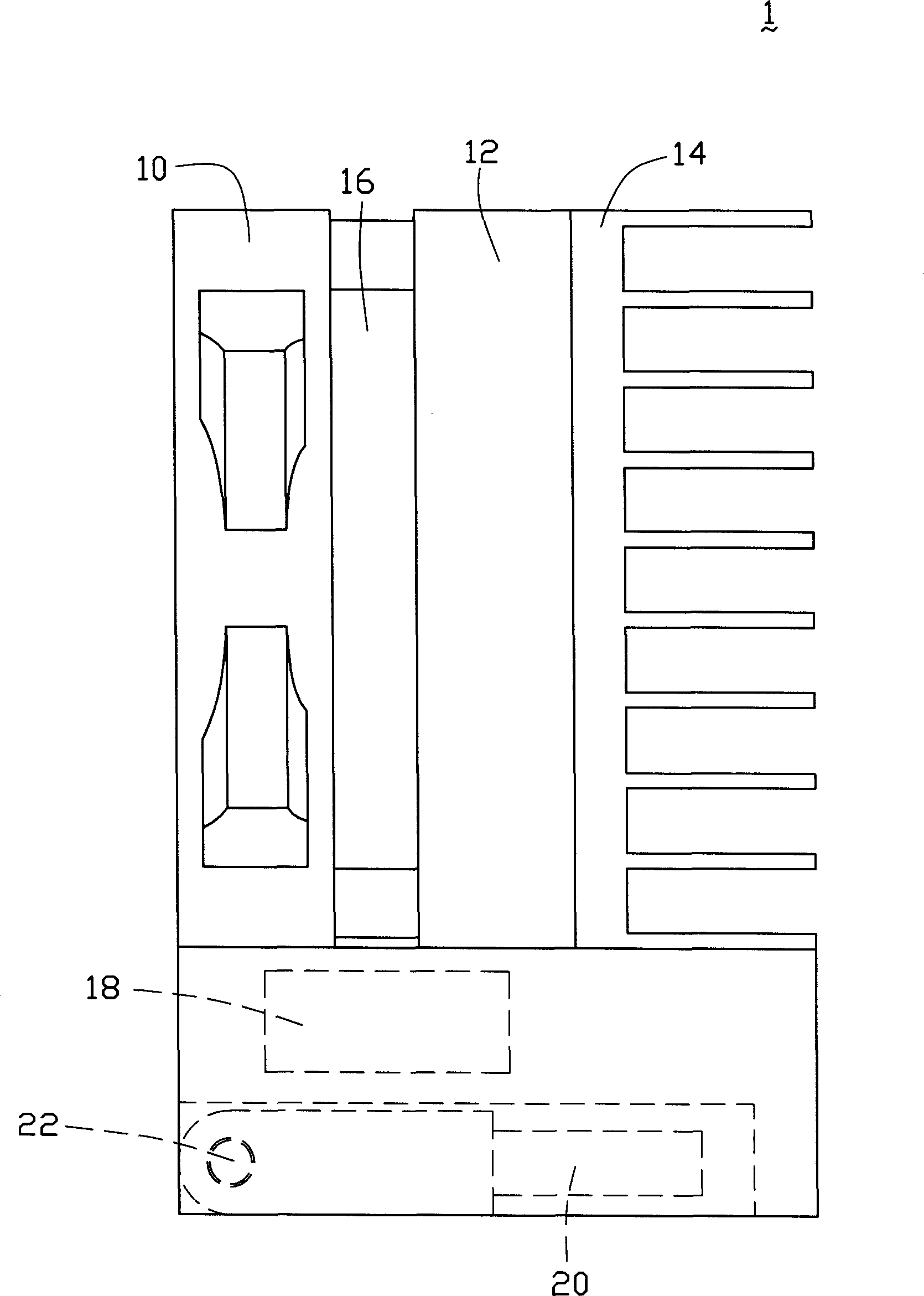
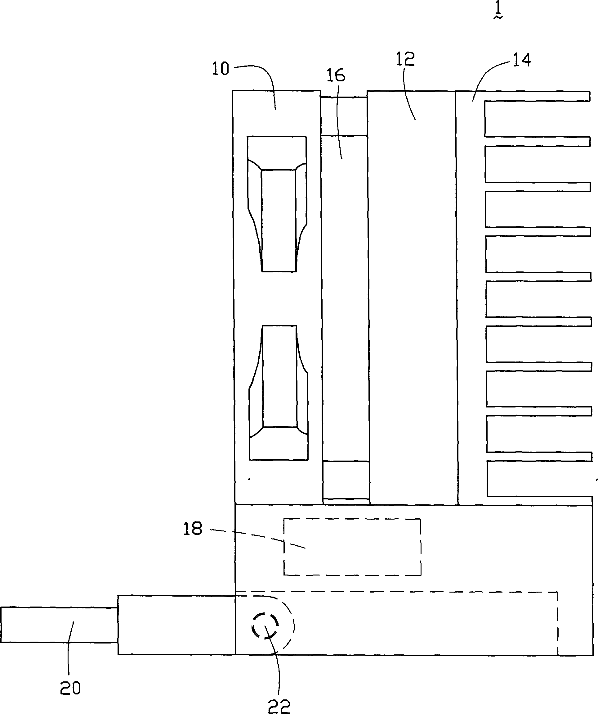
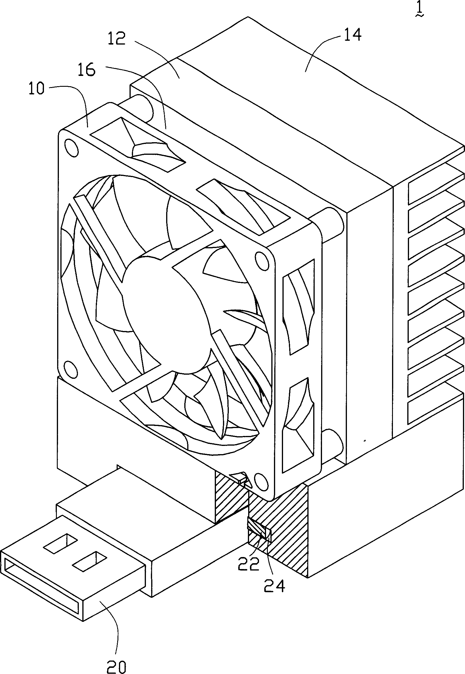
[0017] Such as figure 1 Shown is a heat dissipation device 1 of a preferred embodiment of the present invention, which includes an axial fan 10, a thermoelectric cooling device (Thermo-Electric Cooler, TEC) 12, a single-chip processing device 18, and an interface terminal 20 . The thermoelectric cooling device 12 is arranged in the axial air inlet direction of the axial flow fan 10 , its cold end is connected with the axial flow fan 10 , and its hot end is provided with cooling fins 14 . A gap 16 is provided between the axial fan 10 and the thermoelectric cooling device 12 as an air inlet of the axial fan 10 . The single-chip processing device 18 is electrically connected to the axial fan 10 and the thermoelectric cooling device 12 , and is used to control the speed of the axial fan 14 and the power of the single-chip processing device 18 . The interface terminal 20 includes a free end (not marked) and a fixed end (not marked) corresponding to the free end. The interface te...


PUM


Abstract

Disclosed is a heat dissipating device installed outside of an electronic device. The inventive device comprises a fan, a heat electronic cooling device, a processing device and an interface terminal. Wherein the heat electronic cooling device is set on the direction of fan air inlet and has an air inlet gap between the fan; the processing device is connected with the fan and the heat electronic cooling device separately to control fan rotary speed and power of the heat electronic cooling device; the heat dissipating device is connected with the electronic device via the interface terminal. Also disclosed is a heat dissipating method which comprises: the heat dissipating device obtaining necessary power source via an interface terminal; the processing device of the heat dissipating device obtaining electronic device temperature and controlling fan rotary speed of the heat dissipating device and power of the heat electronic cooling device. The inventive device and method has the advantages of having high heat dissipating efficiency.

Description

【Technical field】 [0001] The invention relates to a heat dissipation device and method, in particular to a heat dissipation device and method for electronic equipment. 【Background technique】 [0002] With the improvement of the performance of electronic equipment (such as notebook computers), the operating frequency of the components used in it is getting higher and higher, and the corresponding heat generated is also increasing. If the corresponding cooling device is not supplemented, the life of each component of the system will be reduced, and system stability will also be affected. There are many existing heat dissipation technologies for electronic equipment, such as heat dissipation plates, fan heat dissipation, keyboard heat dissipation, automatic temperature control, and metal frames. In order to achieve better heat dissipation performance, some electronic devices use multiple heat dissipation technologies at the same time. For example, automatic temperature contro...

Claims


Application Information

Patent Timeline
Patent Type & Authority Applications(China)
IPC IPC(8): G06F1/20
CPCG06F1/1632G06F1/206G06F1/203F25B2321/0211F25B2321/0251F25B21/02
Inventor 李欣和
Owner HONG FU JIN PRECISION IND (SHENZHEN) CO LTD
Why Eureka
Try Eureka