
Plasma display apparatus

A display device and plasma technology, which is applied in the direction of AC plasma display panels, identification devices, electrode configuration, etc., can solve the problems of blocking visible light discharge space, luminous efficiency and brightness reduction, and achieve the effect of improving efficiency

Inactive Publication Date: 2006-12-13
LG ELECTRONICS INC
View PDF0 Cites 0 Cited by
  • Summary
  • Abstract
  • Description
  • Claims
  • Application Information

AI Technical Summary

Problems solved by technology

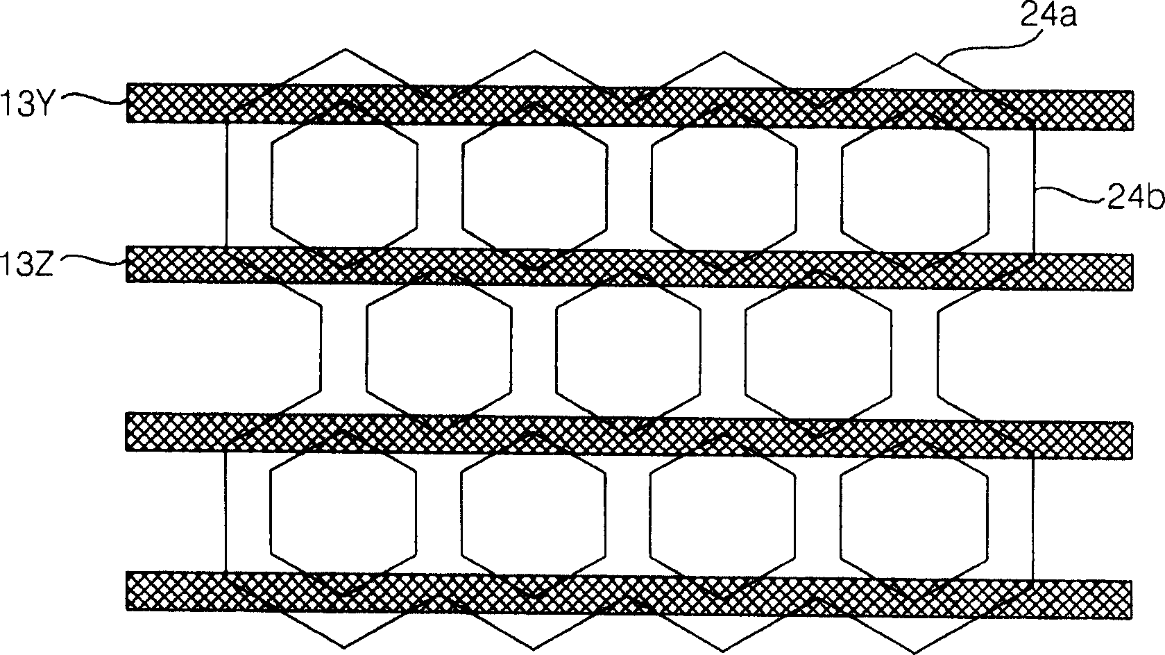
[0014] image 3 The shown hexagonal Δ partition has the advantage of increasing the coating area of ​​the phosphor, but since the bus electrodes 13Y and 13Z formed overlapping with the first partition 24a block the discharge space for emitting visible light, there is a problem of lower luminous efficiency and brightness. question

Method used


Image

  • Plasma display apparatus
  • Plasma display apparatus
  • Plasma display apparatus

Examples


Embodiment Construction

[0041] Embodiments of the delta-shaped discharge cell and the electrode structure of the discharge cell in the plasma display panel of the present invention will be described below with reference to the drawings.

[0042] However, there are many embodiments of the delta-shaped discharge cell and the plasma display panel having the electrode structure of the discharge cell according to the present invention, and therefore are not limited to the embodiments described in this specification.

[0043] Figure 4 is a cross-sectional view illustrating the structure of the delta-shaped discharge cell of the present invention, Figure 5 and Figure 6 It is a figure which shows the electrode structure of the said Δ-shaped discharge cell.

[0044] The plasma display devices according to the first to fourth embodiments of the present invention have a delta-shaped structure in which discharge cells arranged vertically adjacent to each other form one pixel cell.

[0045] That is, the pla...


PUM

PropertyMeasurementUnit
Separation distanceaaaaaaaaaa

Abstract

A plasma display apparatus is provided. Polygonal discharge cells are arranged in delta. Extension parts are extended from pairs of sustain electrodes that apply a voltage to the discharge cells to discharge spaces to face each other. Since the extension parts have at least one depressed parts, the efficiency of sustain discharge improves due to a long gap. Since the width of data electrodes formed under the discharge cells is large in the discharge spaces, a distance between the effective side surfaces of the pairs of sustain electrodes and the data electrodes is reduced so that the efficiency of address discharge improves.

Description

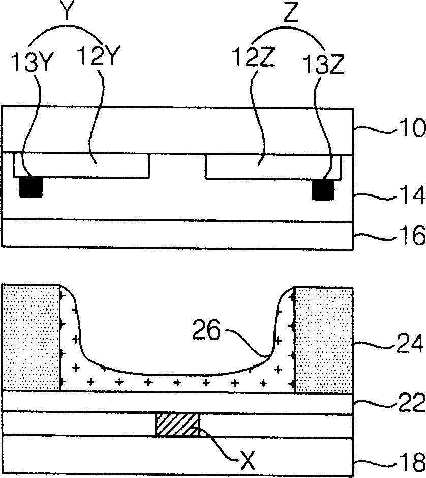
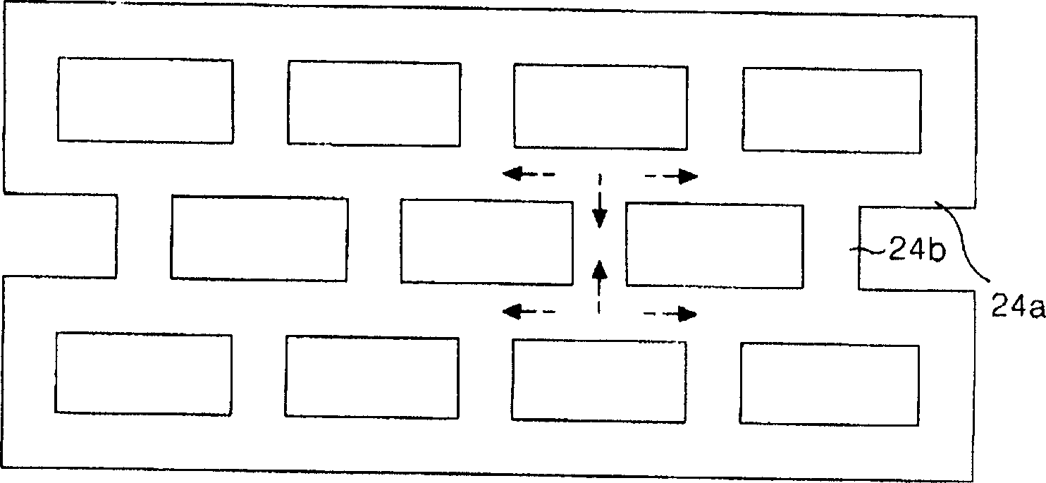
technical field [0001] The present invention relates to a plasma display device, in particular to an electrode structure capable of improving sustain discharge and address discharge efficiency in discharge cells arranged in a delta shape. Background technique [0002] A plasma display device refers to the following device: a discharge cell is formed between a back substrate with a partition wall and a front substrate facing it, and the vacuum ultraviolet rays generated when the inert gas inside each discharge cell is discharged by a high frequency voltage make the phosphor emits light, thereby revealing an image. [0003] figure 1 is a cross-sectional view showing a discharge cell of a typical plasma display panel. [0004] First, the above-mentioned discharge cells are formed by a plurality of barrier ribs 24 defining a discharge space on rear substrate 18 facing front substrate 10 . figure 1 The case where the above-mentioned discharge cells are defined by quadrangular ...

Claims


Application Information

Patent Timeline
IPC IPC(8): H01J17/04H01J17/16H01J17/49G09F9/313H01J11/36H01J11/22
CPCH01J11/12H01J11/24H01J11/32H01J11/36H01J2211/245H01J2211/363H01J2211/365
Inventor 安泳准
Owner LG ELECTRONICS INC
Learn More