HDTV CRT display having optimized kinescope geometry, yoke field and electronic gun orientation

A technology for cathode ray tubes and electron guns, which is applied in the direction of cathode ray tubes/electron beam tubes, circuits, discharge tubes, etc., and can solve problems such as increased inclination of the barrel-shaped magnetic field, distortion of fluorescent points on the screen, etc.

Inactive Publication Date: 2006-12-13
THOMSON LICENSING SA
View PDF1 Cites 2 Cited by
  • Summary
  • Abstract
  • Description
  • Claims
  • Application Information

AI Technical Summary

Problems solved by technology

However, the barrel-shaped magnetic field required to achieve self-convergence at 3 / 9 of the screen increases tilt, resulting in vertically elongated phosphor spots at 3 / 9 and corners of the screen, as shown in the figure of U.S. Patent No. 5,170,102 10 shown
[0011] While improvements have been realized by orienting the electron gun along the vertical or minor axis in self-converging systems, phosphor spot distortion at screen 3 / 9 and corner locations remains a problem

Method used


Image

  • HDTV CRT display having optimized kinescope geometry, yoke field and electronic gun orientation
  • HDTV CRT display having optimized kinescope geometry, yoke field and electronic gun orientation
  • HDTV CRT display having optimized kinescope geometry, yoke field and electronic gun orientation

Examples


Embodiment Construction

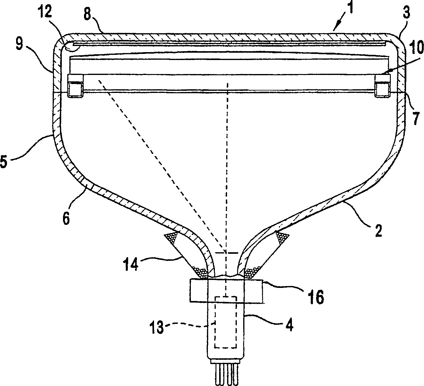
[0019] figure 2 A cathode ray tube (CRT) 1 is shown, for example a W76 widescreen tube, having a glass envelope 2 comprising a rectangular phosphor screen panel 3 and a tubular neck 4 joined by a funnel 5 . The funnel 5 has an inner conductive coating (not shown) extending from the anode button 6 towards the screen panel 3 and to the neck 4 . The screen panel 3 comprises a viewing screen 8 and a peripheral flange or side wall 9 which is sealed to the funnel 5 by frit 7 . The three-color phosphor screen 12 is carried by the inner surface of the phosphor screen panel 3 . The screen 12 is a strip screen having fluorescent strips arranged in groups of three, each of which includes fluorescent strips of three colors each. The shadow mask assembly 10 is detachably installed at a predetermined distance from the screen 12 . Electron gun 13 such as figure 2 Shown schematically by dashed lines in , it is mounted centrally in the neck 4 so as to generate and direct three parallel e...


PUM


Abstract

A cathode ray tube (1) has a faceplate panel (3) with a short axis and a long axis. The faceplate panel has a display screen on the inside of the panel and the panel extends back to a funnel (5) which houses an electron gun system within an integral neck (4). The electron gun system produces co-planar beams arranged in a linear array which is parallel to a short axis of the screen (12). A deflection system (14) is positioned over the neck of the funnel for applying electromagnetic control fields to electron beams emanating from the electron gun system directed toward the screen. The deflection system has a first deflection coil system for generating a substantially barrel shaped magnetic field for deflecting the beams in the direction of the long axis and a second deflection coil system for generating a substantially pincushion magnetic field for deflecting the beams in the direction of the short axis. At least one of the deflection coil systems generates a misconvergence along at least one of the axes parallel to the direction of the co-planar beam. Coils (16) for generating a quadrupolar magnetic field are coupled to the deflection coil systems for correcting misconvergence.

Description

technical field [0001] The present invention relates to a cathode ray tube (CRT) display, and more particularly to such a display with optimized yoke magnetic field, electron gun orientation and related components for high aspect ratio high definition television (HDTV) displays. Background technique [0002] With the continuous development of television technology, high-definition television (HDTV) images can now be transmitted through selected channels. The transmission of HDTV images is expected to continue to grow, and the demand for displays capable of receiving and displaying HDTV images will follow this trend. Along with these developments, the demand for larger aspect ratios, flat screens, and improved image resolution characteristics has increased. Accordingly, there is a need to provide a CRT display with improved image resolution capabilities on large aspect ratio screens capable of displaying HDTV images. [0003] Improves the phosphor dot effect so that the pho...

Claims


Application Information

Patent Timeline
Patent Type & Authority Applications(China)
IPC IPC(8): H01J29/70
CPCH01J29/705
Inventor 罗伯特·L·巴宾
Owner THOMSON LICENSING SA
Why Eureka
Try Eureka