
Method and apparatus for performing an in-mold coining operation

一种模具、压力的技术,应用在注射压缩模制领域,能够解决模具不能被设计成接受型芯型芯等问题

Active Publication Date: 2006-12-20
GENTEX OPTICS
View PDF5 Cites 2 Cited by
  • Summary
  • Abstract
  • Description
  • Claims
  • Application Information

AI Technical Summary

Problems solved by technology

Because CDs are only manufactured in one uniform thickness, molds cannot be designed to accept cores with part-forming surfaces that have different curves or cores that are set at different heights relative to the mold parting line

Method used


Image

  • Method and apparatus for performing an in-mold coining operation
  • Method and apparatus for performing an in-mold coining operation
  • Method and apparatus for performing an in-mold coining operation

Examples


Embodiment Construction

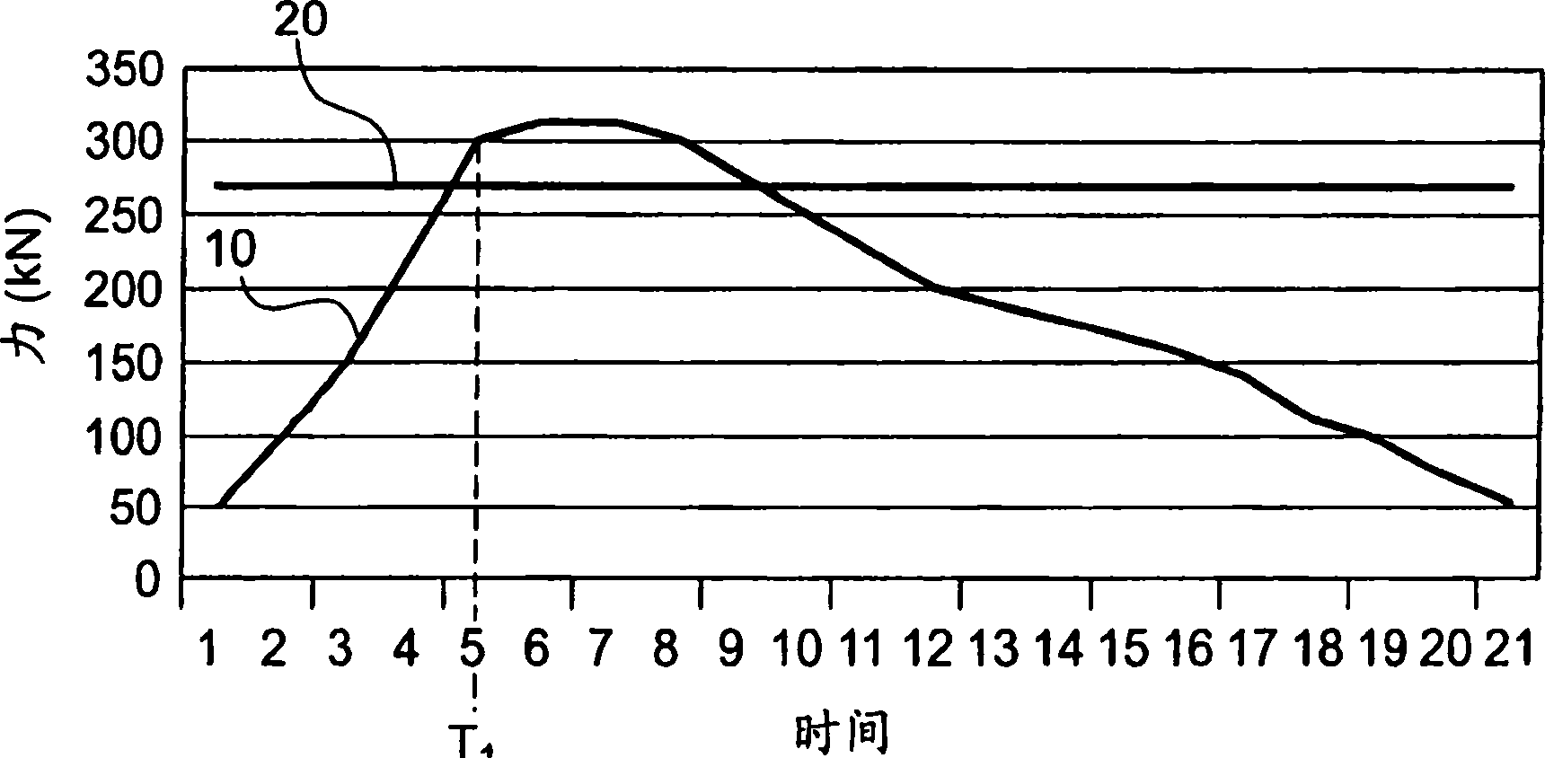
[0021] In general, injection compression molding is characterized by a compression phase in which the core compresses into contact with the molding material as it cools. This compression is reproduced by molding by bringing the core into intimate contact with the molding material as the compressed material shrinks. Components that have different thicknesses across their profile exhibit different degrees of shrinkage based on thickness, like ophthalmic lenses made of polycarbonate.

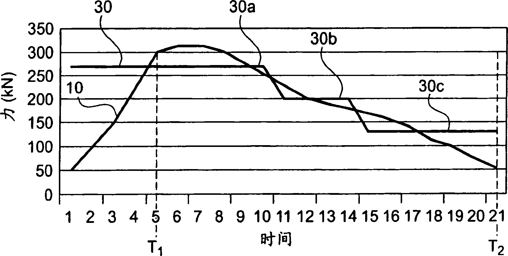
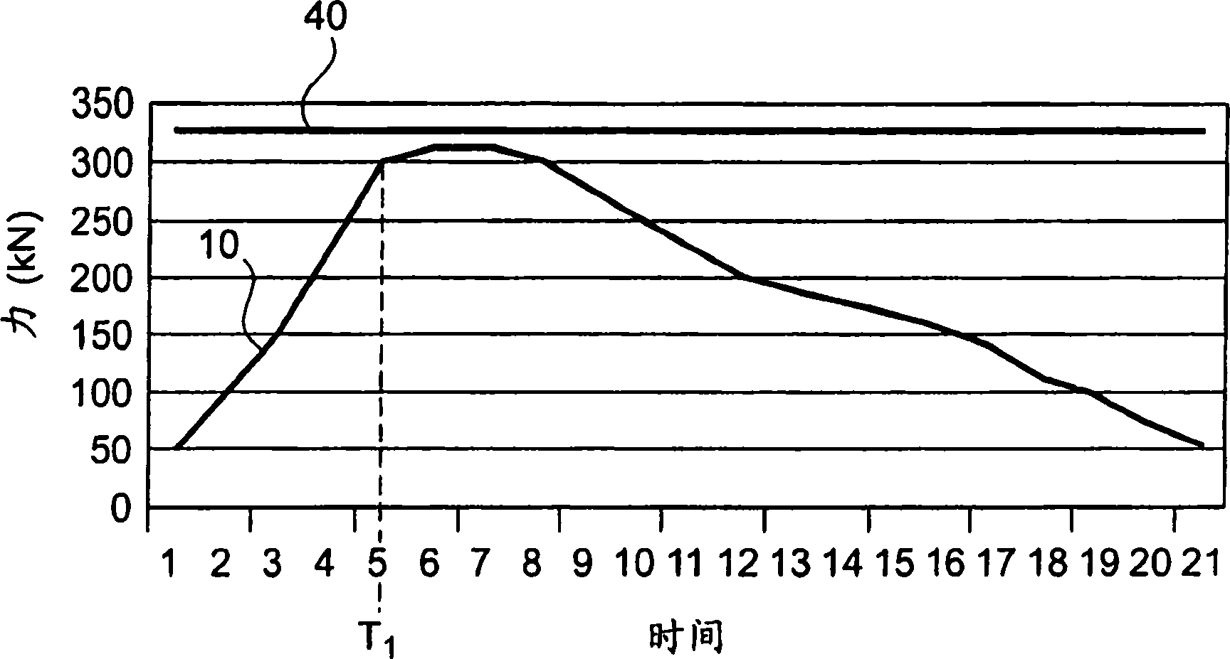
[0022] While compression helps improve mold reproduction, it creates challenges in controlling part thickness. The compression phase automatically changes the distance between the cores, thereby changing the target cavity thickness. One solution to this problem is to secure the core to the mold at the target cavity thickness. Then, in a so-called clamping stop, the entire mold half is displaced or slightly opened during the coining operation.

[0023] Referring now in detail to the drawings, and...


PUM


Abstract

A hardware configuration and related method for performing a coining-type injection compression operation. The invention is useful in molding lenses since lenses have different thicknesses at various points. The equipment maintains the mold in a closed position during the entire molding cycle. A two part standoff post is designed to provide for slight axial compression during high injection pressure. The standoff post also provides a convenient mounting surface near the parting line to install inserts at various heights.

Description

technical field [0001] The present invention relates to methods and apparatus for injection compression molding that provide the benefit of coining without opening the mold. Background technique [0002] US Patent No. 5,417,899 and the article "Simulation of Injection-Compression Molding For Optical Media" by Fan et al. describe prior art coining operations whereby the mold passes at the parting line through a cavity that exceeds the clamping force Pressure to open. This article describes molding as a process in which the cavity thickness is initially set slightly less than the nominal thickness of the part. As the screw moves forward, the chamber pressure and cavity force applied to the machine platen increases. When the force applied to the mold by melting is higher than the clamping force set on the machine, the mold expands open to reduce the pressure in the cavity. The process converts the imposed volumetric flow rate conditions at the nozzle to seal pressure conditi...

Claims


Application Information

Patent Timeline
Patent Type & Authority Applications(China)
IPC IPC(8): B29C45/26B29C45/56B29L11/00
CPCB29C45/561B29C2045/5615B29C2045/563B29D11/00009B29D11/0048
Inventor R·F·小维穆思
Owner GENTEX OPTICS
Features
  • Generate Ideas
  • Intellectual Property
  • Life Sciences
  • Materials
  • Tech Scout
  • Unparalleled Data Quality
  • Higher Quality Content
  • 60% Fewer Hallucinations
Learn More