Method of manufacturing needles for textile machines

A technology of textile machinery and needle latch, which is applied in the field of loop-forming textile machinery needles, can solve the problems that different requirements of mechanical properties are difficult to achieve, and achieve the effect of low reprocessing cost

Active Publication Date: 2006-12-20
HUGO KERN & LIEBERS & PLATINEN & FEDERNFAB
View PDF1 Cites 2 Cited by
  • Summary
  • Abstract
  • Description
  • Claims
  • Application Information

AI Technical Summary

Problems solved by technology

Therefore, different requirements for the mechanical properties of different regions of the needle may be difficult to achieve

Method used


Image

  • Method of manufacturing needles for textile machines
  • Method of manufacturing needles for textile machines
  • Method of manufacturing needles for textile machines

Examples


Embodiment Construction

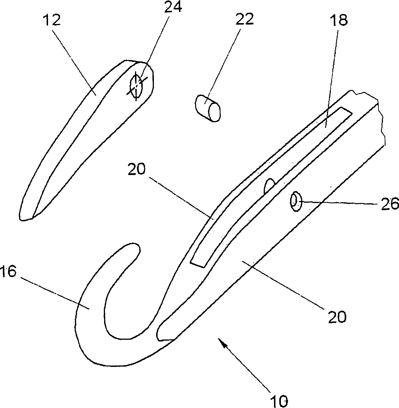
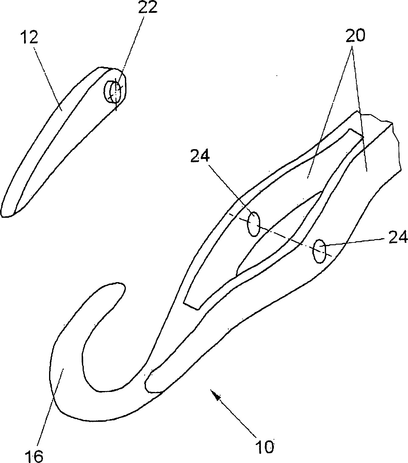
[0032] figure 1 The point of the latch needle is shown in a perspective exploded view. This needle point is made up of needle head 10 and needle latch 12. The needle tip is fixed on a figure 1 On the front end of the needle bar 14 not shown in.

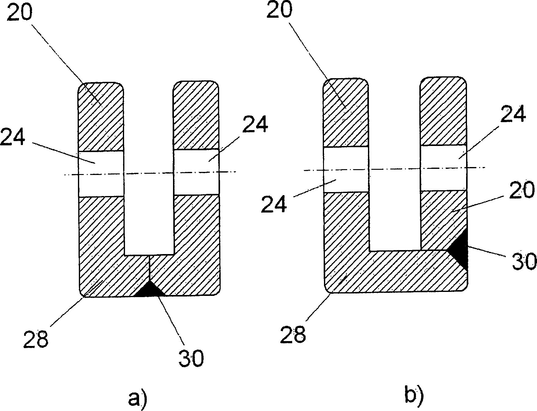
[0033] The needle 10 has a needle hook 16 at its front end. A latch needle groove 18 extending longitudinally is designed in the needle head 10 . The needles form side walls 20 on both sides of the latch needle groove 18 which form the lateral boundaries of the latch needle groove 18 . In a typical case, the width of the needle head 10 measured perpendicularly to the latch needle groove 18 in the area of ​​the latch needle groove 18 is about 0.9 mm. The width of the latch needle groove 18 is about 0.3 mm, so the wall thicknesses of the side walls 20 are respectively about 0.3 mm. The needle latch 12 is rotatably installed in the latch needle groove 18 with its rear end. A pivot pin 22 is used for this purpose, which is rotatabl...


PUM


Abstract

The production process is for textile machine needles which have at least one shaft and a needle tip fitted to the front of the shaft. At least the needle tip is produced by injection molding, in particular by metal injection molding. This may be done by multiple-component injection molding, in particular by two-component injection molding.

Description

technical field [0001] The invention relates to a method according to the preamble of claim 1 for the production of needles for textile machines, in particular for loop-forming textile machines. Background technique [0002] Different types of needles are used in textile machinery such as latch needles, crochet needles, compound needles, plush crochet needles, etc. These needles are conventionally manufactured in such a way that blanks are punched out, which have to be reworked expensively by milling, coining and rounding. An example of this method is described in DE 196 44 166 C1. [0003] In addition to this expensive production method, the mechanical properties of the needle are usually predetermined here by the material of the blank. Therefore, different requirements on the mechanical properties of different regions of the needle may be difficult to achieve. Contents of the invention [0004] It is an object of the invention to provide a method by which mechanically...

Claims


Application Information

Patent Timeline
Patent Type & Authority Applications(China)
IPC IPC(8): D04B35/02B23P15/00B22D17/00B22D25/00
CPCB22F3/225B21G1/04B22F7/06D04B35/04
Inventor K·弗里奇R·黑蒂希R·韦兰特A·塞德尔G·罗森费尔德
Owner HUGO KERN & LIEBERS & PLATINEN & FEDERNFAB
Why Eureka
Try Eureka