Air heat exchange device for air conditioner

A heat exchange device, air technology, applied in air conditioning systems, space heating and ventilation, space heating and ventilation details, etc., can solve problems such as pipeline leakage and failure, increase installation difficulty, reduce refrigeration efficiency, etc. Improve cooling efficiency, reduce power consumption, reduce power consumption effect

Inactive Publication Date: 2006-12-20
SUZHOU QUTU THERMAL CONTROL SYST
View PDF0 Cites 1 Cited by
  • Summary
  • Abstract
  • Description
  • Claims
  • Application Information

AI Technical Summary

Problems solved by technology

[0003] 1. The difficulty of installation is increased, and leakage and failure between pipelines are prone to occur;
[

Method used


Image

  • Air heat exchange device for air conditioner
  • Air heat exchange device for air conditioner
  • Air heat exchange device for air conditioner

Examples


Embodiment

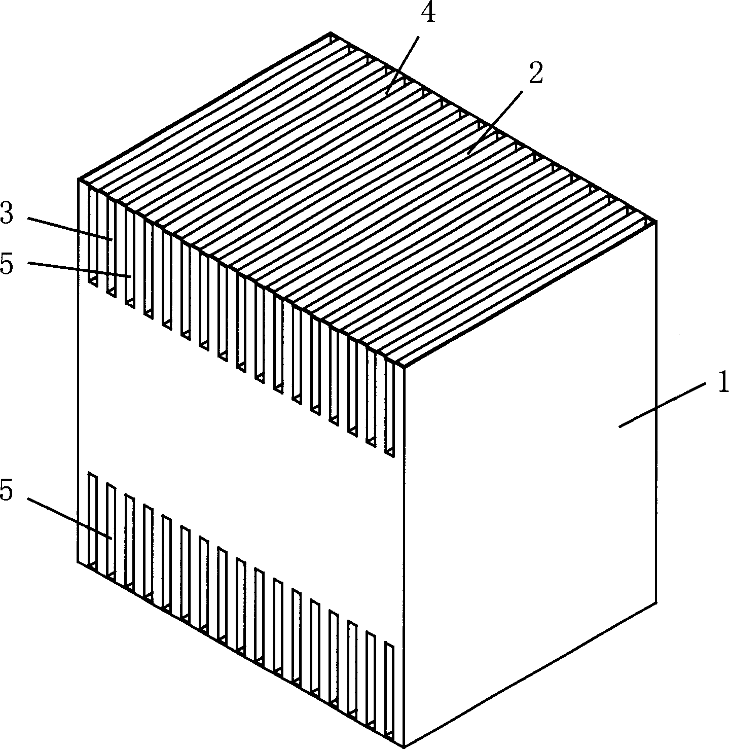
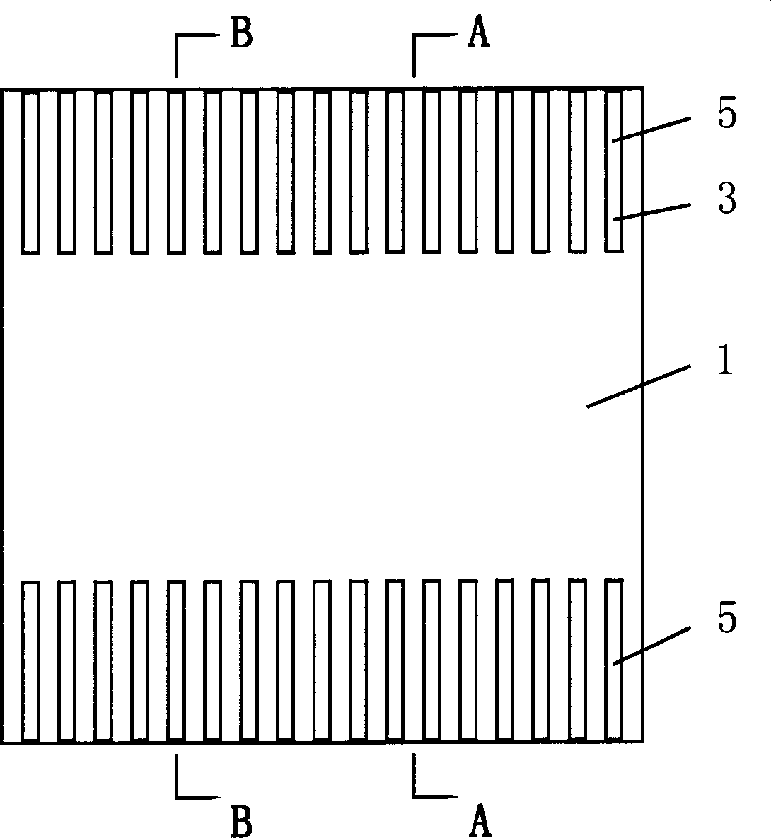
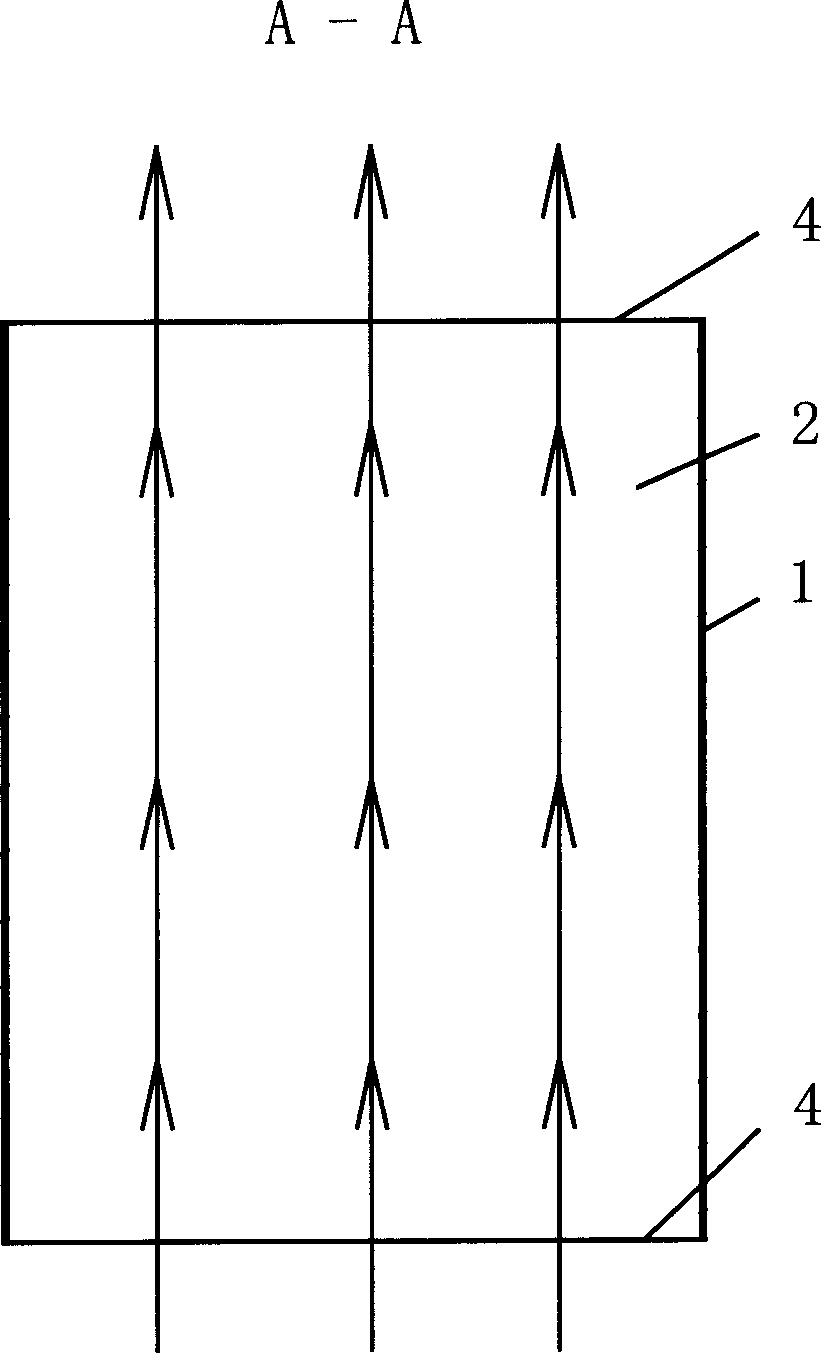
[0021] Example: such as figure 1 , figure 2 , image 3 , Figure 4 As shown, an air-conditioning air heat exchange device includes a body 1, and the body 1 is provided with a plurality of longitudinal cavities 2 and transverse cavities 3 that are arranged side by side and are independent of each other. The longitudinal cavities 2 and the transverse cavities 3 are It is sheet-shaped and arranged at intervals. The inlet and outlet 4 of the longitudinal cavity 2 are located at the main body 1 and the upper and lower ends, and the inlet and outlet 5 of the transverse cavity 3 are located at the front and rear sides of the main body 1 .

[0022] The front wall 6 and the rear wall 7 in the transverse cavity 3 are oppositely provided with several pieces of transverse cantilever partitions 8, which divide the inner cavity of the transverse cavity 3 into an S-shape, and the inlet and outlet 5 of the transverse cavity 3 are located at the same On the side, it can also be located on ...


PUM


Abstract

The invention relates to a heat exchanger of air conditioner, which comprises a main body with several parallel independent longitudinal chambers and horizontal chambers, wherein the entrance of longitudinal chambers are at the main body and upper and lower ends; the entrance of horizontal chambers are at the front and back side surfaces of main body. The invention has two independent channels as indoor air and outdoor air, mounted inside special air conditioner, to utilize the outdoor air via heat exchange to cool the indoor air, and send the indoor air to the vaporized to be cooled more, to improve the refrigerating efficiency and reduce the electricity consumption.

Description

technical field [0001] The invention relates to an air-conditioning air heat exchange device. Background technique [0002] At present, most of the special air conditioners for computer rooms on the market are split-type air conditioners, that is, there are two parts: an indoor unit and an outdoor unit. The indoor unit and the outdoor unit are connected by pipelines. The disadvantages are: [0003] 1. It increases the difficulty of installation and is prone to leakage and failure between pipelines; [0004] 2. The pipeline is exposed to the air, which reduces the cooling efficiency and increases the power consumption. [0005] Therefore, in recent years, integrated computer room special air conditioners have appeared on the market, that is, the indoor unit and the outdoor unit are integrated, which not only improves the cooling efficiency, but also reduces the difficulty of installation. Contents of the invention [0006] The object of the present invention is to provide...

Claims


Application Information

Patent Timeline
IPC IPC(8): F24F1/02F28D7/00F24F13/00
Inventor 刘明国
Owner SUZHOU QUTU THERMAL CONTROL SYST
Why Eureka
Try Eureka