Automatic focusing device for lens

An autofocus and lens technology, applied in focusing device, installation, optics, etc., can solve the problems of complex mechanical structure, large volume, high cost, etc.

Inactive Publication Date: 2006-12-20
POWERGATE OPTICAL INC
View PDF0 Cites 13 Cited by
  • Summary
  • Abstract
  • Description
  • Claims
  • Application Information

AI Technical Summary

Problems solved by technology

Not only makes the mechanical structure complex, but also has the disadvantages of cumbersome and difficult

Method used


Image

  • Automatic focusing device for lens
  • Automatic focusing device for lens
  • Automatic focusing device for lens

Examples


Embodiment Construction

[0016] In order to have a further cognition and understanding of the features, purposes and functions of the present invention, the detailed description is as follows in conjunction with the accompanying drawings:

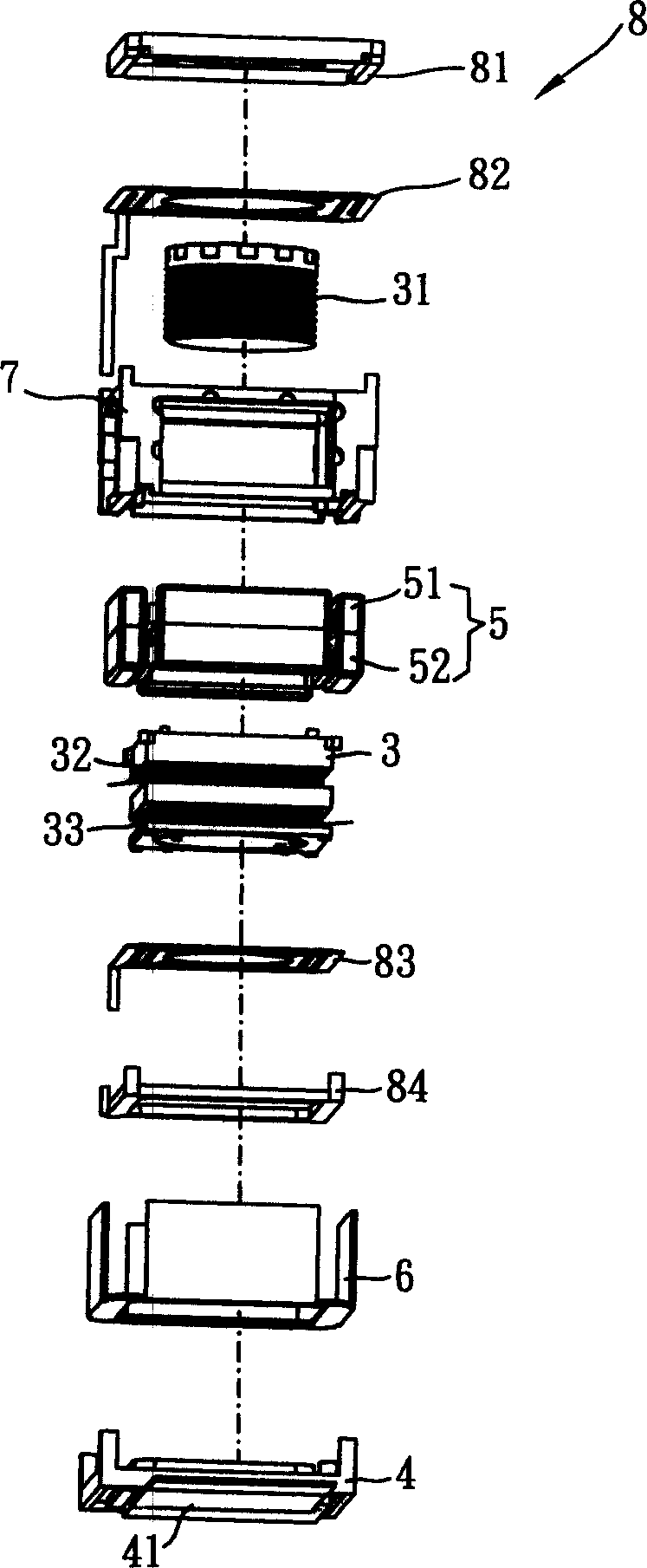
[0017] see image 3 , Figure 4 and Figure 5 , which is a preferred embodiment of the lens autofocus device of the present invention. in, image 3 Shown is a three-dimensional exploded view of the lens auto-focus device of the present invention. Figure 4 It is a schematic diagram of the winding appearance of the lens group seat coil in the lens auto-focus device of the present invention. Figure 5 It is a schematic diagram of the magnetic action in the lens auto-focus device of the present invention.

[0018] Such as image 3 As shown, the lens autofocus device of this embodiment is mainly composed of a lens group holder 3 (Lens-holder), an optical sensor assembly holder 4 (Sensor-holder), a permanent magnet group 5 (Magnets), a yoke 6 ( Yoke) and subject ...


PUM


Abstract

The invention discloses a lens self-focusing device, which comprises the following parts: lens group holder, optical sensing component holder, permanent magnet group, yoke piece and host, wherein one lens group is set on the lens group holder, which is winded by at least two coils of driving coil with inversing-winding direction for two adjacent coils; one optical sensing component is fixed on the optical sensing component holder; the permanent magnet group is composed of upper and lower two-pole permanent magnet with at least two permanent magnet, which is set as the periphery of lens group holder on the yoke piece to form a closed circuit magnetic frame corresponding to at least two coils. The invention improves efficiency of magnetic motion, which saves power to improve waiting and using time for product.

Description

technical field [0001] The invention relates to a lens auto-focus device, especially a camera device, by setting at least two driving coils and the winding directions of two adjacent coils are opposite, and constituted by at least two permanent magnets up and down The two poles of the permanent magnets cooperate with each other to achieve the functions of moving the lens through magnetic force and auto-focusing. Background technique [0002] A general photographing device 1 mainly includes a lens group 11 , a light sensing component 12 and a focusing mechanism (not shown). Wherein the lens group 11 can image the reflected light of the subject on the light sensing component 12 (such as figure 1 shown). Because if the distance between the lens group 11 and the light sensing component 12 is fixed, it can only clearly present objects with a hyperfocal distance of 2-3 meters. If the close-up function is desired, the distance between the lens group and the light sensing compone...

Claims


Application Information

Patent Timeline
IPC IPC(8): G03B13/32G02B7/28
Inventor 张吉龙徐懋仁
Owner POWERGATE OPTICAL INC
Why Eureka
Try Eureka