Supercharge Your Innovation With Domain-Expert AI Agents!

Built-in antenna structure

An antenna structure and built-in technology, applied in the field of antenna structure, can solve problems such as occupying difficult assembly space, affecting the design direction of equipment miniaturization, and affecting antennas

Inactive Publication Date: 2006-12-20
WHA YU IND CO LTD
View PDF0 Cites 2 Cited by
  • Summary
  • Abstract
  • Description
  • Claims
  • Application Information

AI Technical Summary

Problems solved by technology

[0004] The purpose of the present invention is to solve the problem that when the existing antenna is built into the electronic equipment, it is easy to be touched by metal components and affect the characteristics of the antenna, and at the same time, it also increases the difficulty of assembly and the occupation of assembly space affects the design direction of equipment miniaturization To solve the problem, provide a built-in antenna structure that can effectively prevent the metal components inside the electronic device from affecting the antenna characteristics, easy to assemble, and occupy a small space

Method used


Image

  • Built-in antenna structure
  • Built-in antenna structure
  • Built-in antenna structure

Examples


Embodiment Construction

[0015] The present invention will be described in further detail below in conjunction with the accompanying drawings.

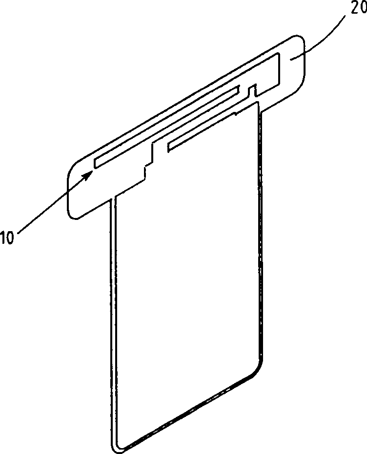
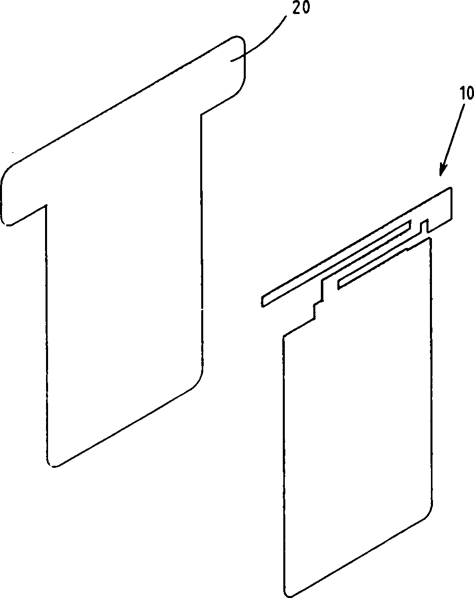
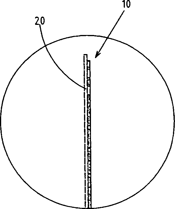
[0016] see Figure 1 to Figure 6 The built-in antenna structure of the present invention includes an antenna part 10 and an insulating layer 20 fixedly arranged on the antenna part, so that the antenna part 10 and the insulating layer 20 together form a multilayer structure; the insulating layer 20 can be plastic or other insulating materials, and can be fixedly combined with the antenna part 10 by a single or multi-layer insulating layer 20; see Figure 4 , the insulating layer 20 can also be fixedly arranged on the front and back sides of the antenna part 10; see Figure 5 According to the spatial characteristics inside the wireless transceiver device 30 , the insulating layer 20 can be fixedly arranged at a local position of the antenna part 10 .

[0017] Corresponding to the following beneficial effect analysis for the above structural description of th...


PUM


Abstract

The invention relates to an internal antenna structure, belonging to the internal antenna of wireless signal receiving / sending device, for solving the problem that internal antennal is easily to be contacted by metallic element to affect the property of antenna, to improve the assembly, wherein one side surface of antenna part is fixed with one insulated layer; said antenna part and insulated layer form one multilayer antenna structure, widely used in variable wireless signal receiving / sending devices.

Description

technical field [0001] The invention relates to an antenna structure, in particular to a built-in antenna structure. Background technique [0002] At present, wireless communication technology that uses electromagnetic waves to transmit signals has been widely used in mobile phones, laptop computers, and other devices with wireless information sending and receiving functions. Therefore, the antenna used to induce electromagnetic waves is an extremely important component of wireless communication equipment. The antennas used in wireless transceiver equipment are external, which hinders the design direction of equipment miniaturization and aesthetics. At the same time, it also makes the antennas vulnerable to external collisions and breakage. Therefore, wireless communication equipment adopts built-in antennas, which has become a variety of A common practice in wireless transceiver equipment. [0003] However, the above-mentioned wireless transceiver devices are full of vario...

Claims


Application Information

Patent Timeline
Patent Type & Authority Applications(China)
IPC IPC(8): H01Q1/38
Inventor 张毅华邱宏献
Owner WHA YU IND CO LTD
Features
  • R&D
  • Intellectual Property
  • Life Sciences
  • Materials
  • Tech Scout
  • Unparalleled Data Quality
  • Higher Quality Content
  • 60% Fewer Hallucinations
Learn More