Multi-channel multiplexing cascade integrating comb filter

A technology of cascading integral combs and filters, which is applied in the direction of modulated carrier system, impedance network, digital technology network, etc., can solve the problem of large realization area and achieve the effect of cost saving

Inactive Publication Date: 2006-12-20
ZTE CORP
View PDF0 Cites 4 Cited by
  • Summary
  • Abstract
  • Description
  • Claims
  • Application Information

AI Technical Summary

Problems solved by technology

[0004] The purpose of the present invention is to overcome the filter in FPGA or ASIC that must use multiple cascaded integral comb filters to convert the da...

Method used


Image

  • Multi-channel multiplexing cascade integrating comb filter
  • Multi-channel multiplexing cascade integrating comb filter
  • Multi-channel multiplexing cascade integrating comb filter

Examples


Embodiment Construction

[0015] Below in conjunction with accompanying drawing, the implementation of technical scheme is described in further detail according to the order of accompanying drawing:

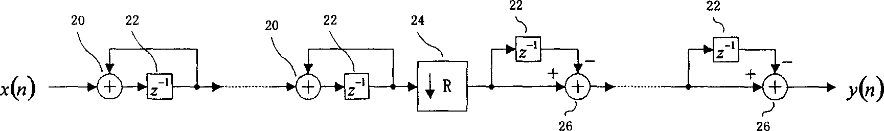
[0016] figure 1 It is a structure diagram of a classic cascaded integral-comb filter capable of decimating a single-channel data rate. It can be seen from the figure that the decimator 24 with a decimation rate of R is in the middle, the left side of the decimator is an integrator composed of an adder 20 and a delay unit 22, and the right side is a differentiator composed of a subtractor 26 and a delay unit 22. The order of the filter refers to the number of integrators and differentiators. For example, a 4-stage cascaded integral comb decimation filter means that there are 4 integrators on the left side of the decimator and 4 differentiators on the right side.

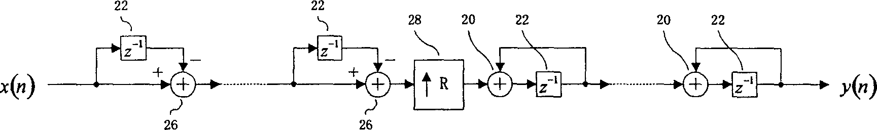
[0017] figure 2 It is a structure diagram of a classic cascaded integral comb filter that can interpolate the data rate of a single channel....


PUM


Abstract

The invention relates to a cascade integral comb filter, which uses shift register to overcome the defects of traditional cascade integral comb filter which only can transform the data speed of one channel, to need distributing cascade integral comb filter for each channel when transforming the data speed of several channels, to cause over-large area in FPGA or ASIC. With affecting property, the invention can transform the data speed of several channels with only one cascade integral comb filter, to reduce the realize area of FPGA or ASIC, and save cost.

Description

technical field [0001] The invention relates to the field of wireless communication, in particular to sampling rate conversion in digital frequency synthesis technology. Background technique [0002] At present, in the field of wireless communication, digital frequency synthesis technology is used more and more widely. Before digital quadrature modulation, it is necessary to perform interpolation filtering on the baseband digital signal to increase its data rate; or after digital quadrature demodulation, it is necessary to perform decimation filtering on the baseband digital signal to reduce its data rate. The cascaded integral comb filter proposed by Hogenaue (E.B.Hogenauer.An economical class of digital filters for decimation and interpolation.IEEE Transactions on Acoustics, Speech and Signal Processing, ASSP-29(2):155-162, 1981) has a simple structure, It has the advantages of being regular and requiring a small amount of storage, and it does not require a multiplier. In...

Claims


Application Information

Patent Timeline
IPC IPC(8): H04L27/00H03H17/02
Inventor 毛惠敏曾代兵
Owner ZTE CORP
Why Eureka
Try Eureka