
Hybrid TEM/birdcage coil for MRI

A birdcage and coil technology, applied in the field of magnetic resonance technology and magnetic resonance imaging, can solve the problems of complex movement and insertion of different coils, achieve high radio frequency characteristics, and improve the effect of radio frequency characteristics

Inactive Publication Date: 2006-12-20
KONINKLIJKE PHILIPS ELECTRONICS NV
View PDF1 Cites 17 Cited by
  • Summary
  • Abstract
  • Description
  • Claims
  • Application Information

AI Technical Summary

Problems solved by technology

However, cylindrical full-body birdcage or TEM coils often enclose the patient bridge, or other components, complicating the movement and insertion of the various coils

Method used


Image

  • Hybrid TEM/birdcage coil for MRI
  • Hybrid TEM/birdcage coil for MRI
  • Hybrid TEM/birdcage coil for MRI

Examples


Embodiment Construction

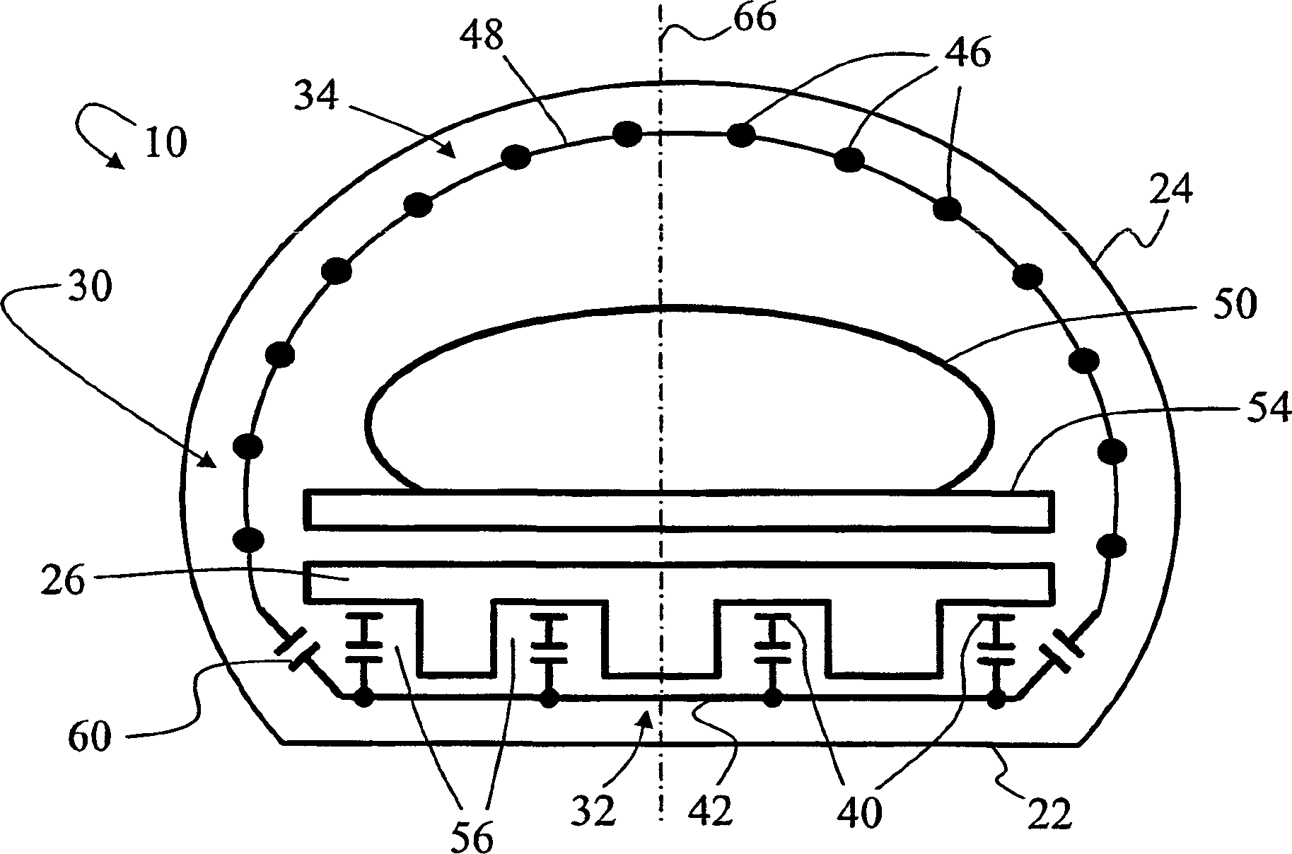
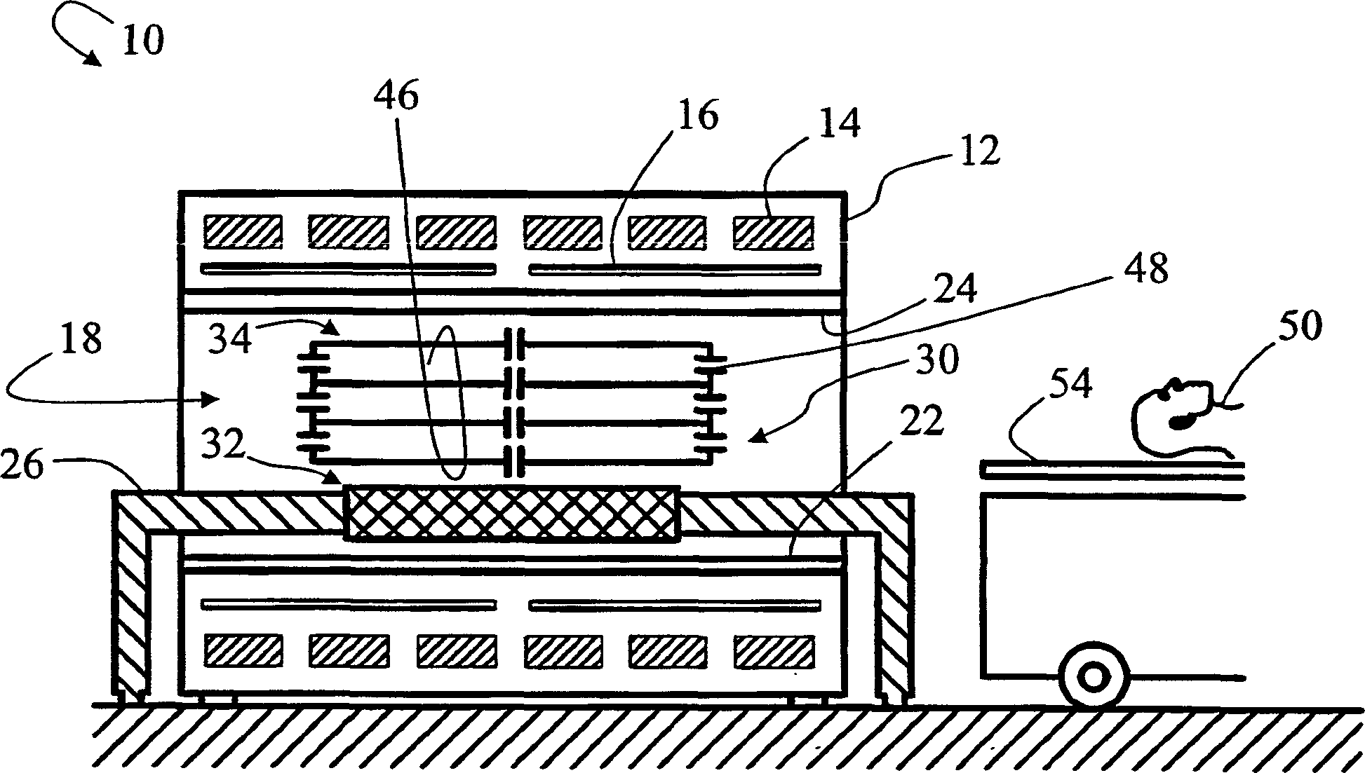
[0028] refer to figure 1 and 2 , in one embodiment, the magnetic resonance scanner 10 includes a main housing 12 that houses or supports at least a main magnetic field coil 14 and a magnetic field gradient coil 16 . The main magnetic field coil 14 generates the main magnetic field B along the magnet cavity 18 defined by the housing 12 0 , while the magnetic field gradient coil 16 generates a selected magnetic field gradient in the magnet cavity 18 .

[0029] The shielding radio frequency isolation enclosure generally extending with the magnet cavity 18 includes a generally planar bottom portion 22 and an arcuate upper portion 24 . An object bridge 26 extends through the cavity 18 and is seated above the generally planar bottom portion 22 of the shielding radio frequency isolation enclosure. In another embodiment, the shielding radio frequency isolator is cylindrical.

[0030] The radio frequency coil 30 includes a generally planar bottom transverse electromagnetic (TEM) po...


PUM


Abstract

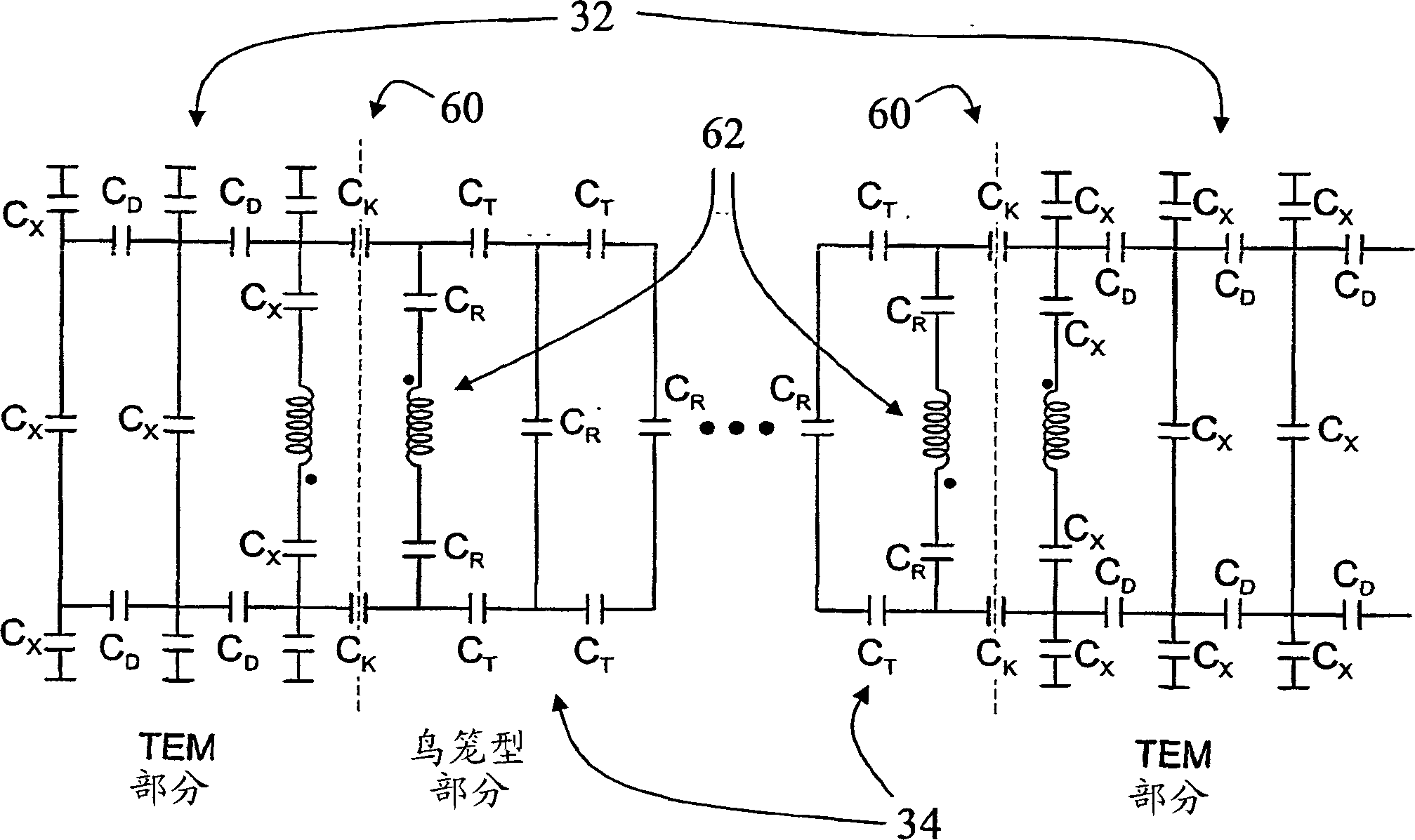
A radio frequency coil (30, 30', 120, 120') for a magnetic resonance imaging system (10, 10'') includes a birdcage section (34, 122, 122') having a plurality of parallel spaced apart conductors (46, 130, 130') and one or more cross or end conductors (48, 132, 144', 154, 156) aligned generally transverse to the spaced apart conductors (46, 130, 130'), and a TEM section (32, 32', 32'', 124, 124') having a plurality of parallel spaced apart conductors (40, 40', 140) and a radio frequency screen (42, 142, 144, 144'). The birdcage section (34, 122, 122') and the TEM section (32, 32', 32'', 124, 124') resonate at a birdcage resonant frequency and a TEM resonant frequency, respectively. The birdcage section (34, 122,122') and the TEM section (32, 32', 32'', 124, 124') are relatively disposed with the parallel spaced apart conductors of each section aligned and define a subject receiving region.

Description

technical field [0001] What follows is the magnetic resonance technique. It can be specifically applied to magnetic resonance imaging, and will be described in conjunction with the specific instructions therein. However, the technique can also be applied in magnetic resonance spectroscopy and other magnetic resonance applications. Background technique [0002] Two types of radiofrequency coils commonly used in magnetic resonance imaging are birdcage coils and transverse electromagnetic (TEM) coils. Each coil has its own advantages and disadvantages. [0003] A birdcage coil consists of a plurality of parallel spaced apart conductors (sometimes referred to as "runners") on the surface of a cylinder with terminal conductors in the form of end caps and a ring or a pair of rings transverse to the rungs. The resonant mode of these coils is typically a single bulk resonator with current flowing from rung to rung. Birdcage coils have an open geometry that is non-clustrophobic t...

Claims


Application Information

Patent Timeline
IPC IPC(8): G01R33/34
CPCG01R33/34046
Inventor C·G·罗伊斯勒
Owner KONINKLIJKE PHILIPS ELECTRONICS NV
Learn More