Surface polishing method for protective side edge of group II-VI semiconductor material

A surface polishing, semiconductor technology, used in surface polishing machine tools, semiconductor/solid-state device manufacturing, grinding/polishing equipment, etc., can solve problems such as crack defects, gaps, debris, etc.

Active Publication Date: 2006-12-27
SHANGHAI INST OF TECHNICAL PHYSICS - CHINESE ACAD OF SCI
View PDF0 Cites 7 Cited by
  • Summary
  • Abstract
  • Description
  • Claims
  • Application Information

AI Technical Summary

Problems solved by technology

In the above first step of polishing process, since the bottom polishing disc is made of a slightly harder glass material, the polishing liquid is always firstly squeezed dir...

Method used


Image

  • Surface polishing method for protective side edge of group II-VI semiconductor material
  • Surface polishing method for protective side edge of group II-VI semiconductor material
  • Surface polishing method for protective side edge of group II-VI semiconductor material

Examples


Embodiment Construction

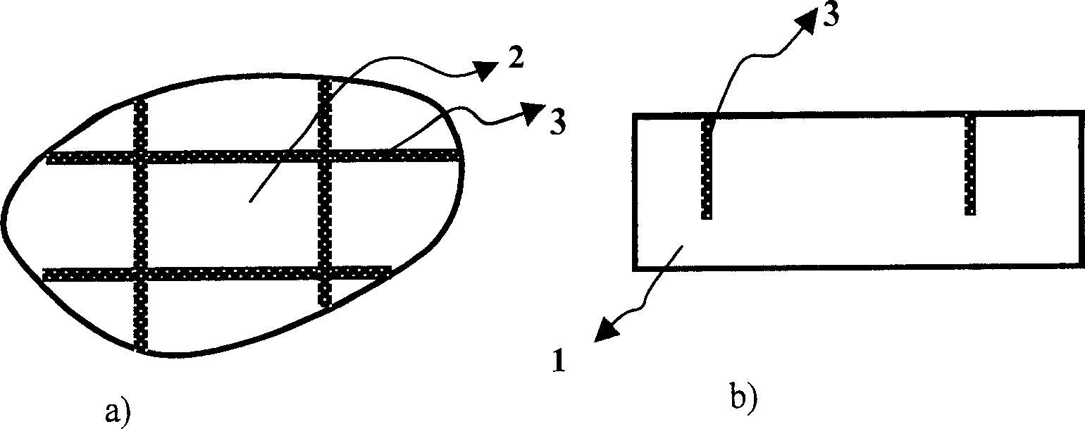
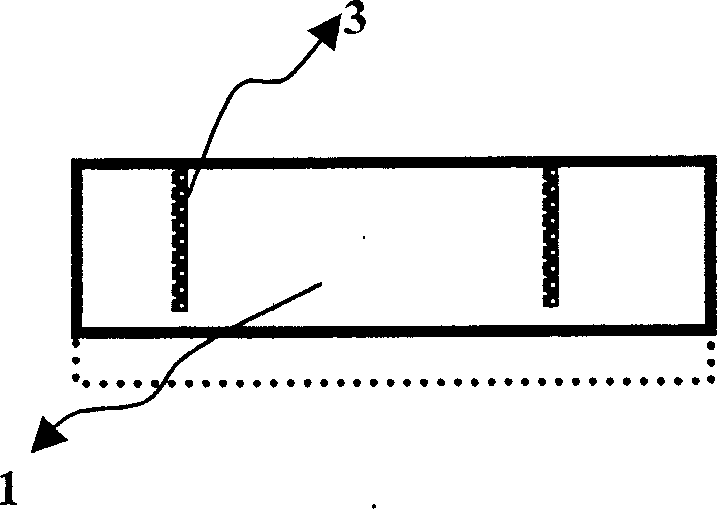
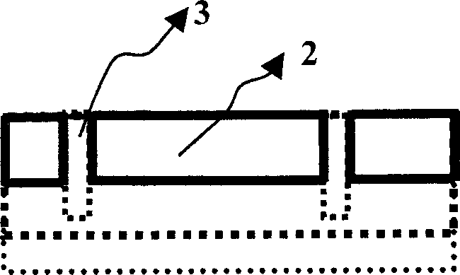
[0018] Take the CdZnTe wafer as an example below for a detailed introduction:

[0019] As shown in the attached figure, the thickness of the original chip 1 is 1100 microns, and the thickness of the molded wafer 2 is required to be 550 microns. First, use a dicing machine to draw the area required for the molded wafer on the surface of the original film, such as 20 mm X 30 mm, and cut the slit 3 The depth is about 600 microns, and then put wax on the surface of the original film with slits and heat it to 70 ° C. After the wax melts and sticks to the flat glass substrate, the surface of the original film is treated with a 3 micron alumina suspension. Coarse mechanical grinding, when grinding to a thickness of 608-610 microns, then mechanical chemical polishing until the required thickness of 550 microns can be obtained to obtain a CdZnTe molded wafer with no damage to the side edge. Finally, after heating to soften the wax, take out the molded wafer part in the central area, an...


PUM


Abstract

Disclosed is a polishing method for protection of group II-VI semiconductor materials side edge by carving out but not penetrating demanded forming wafer area on the original wafer and polishing same. That is, peripheral small wafer is used as teat wafer to be polished, thus, the peripheral small wafer can prevent the extrusion between the middle forming wafer edge and abrasive materials and the chip, gapping, and defect can be prevented caused by extrusion, as a result, the protection of side edge can be realized.

Description

technical field [0001] The invention relates to a semiconductor material surface processing method, in particular to a surface polishing method for protecting side edges of II-VI group semiconductor materials such as cadmium telluride (CdTe), cadmium zinc telluride (CdZnTe) and other infrared optical materials. Background technique [0002] The performance improvement of modern mercury cadmium telluride (MCT) infrared focal plane devices comes from the continuous progress of material growth technology on the one hand, and the continuous deepening of material processing and device process on the other hand. MCT thin film material preparation technologies include molecular beam epitaxy (MBE), vertical immersion liquid phase epitaxy (VLPE), metal organic vapor deposition (MOCVD) and horizontal boat liquid phase epitaxy (HLPE), among which the most mature preparation The technology is HLPE, and the MCT film material grown by this technology has been widely used in various satell...

Claims


Application Information

Patent Timeline
IPC IPC(8): B24B29/02H01L21/304
Inventor 方维政徐琰孙士文周梅华刘从峰涂步华杨建荣何力
Owner SHANGHAI INST OF TECHNICAL PHYSICS - CHINESE ACAD OF SCI
Why Eureka
Try Eureka