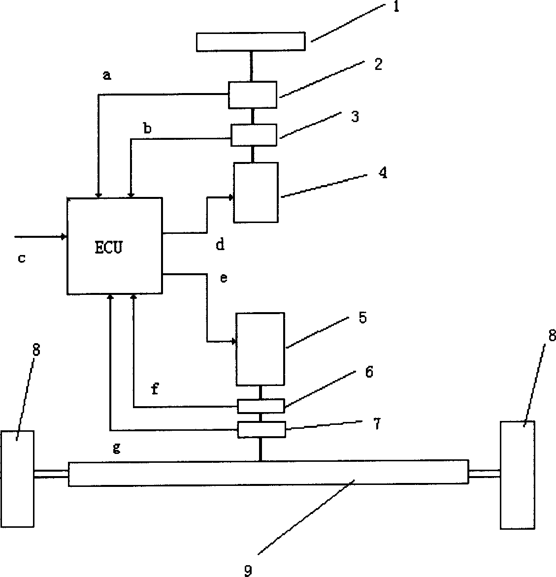
Steering mechanism for vehicular drive-by-wire system and its steering drag simulator
A technology of steering mechanism and steering resistance, applied to electric steering mechanism, etc., can solve the problems of increasing the difficulty of processor ECU, complex control, and complex system control algorithm development, so as to reduce the complexity of research and development, save hardware costs, and simplify The effect of control
- Summary
- Abstract
- Description
- Claims
- Application Information
AI Technical Summary
Problems solved by technology
Method used
Image
Examples
Embodiment 1
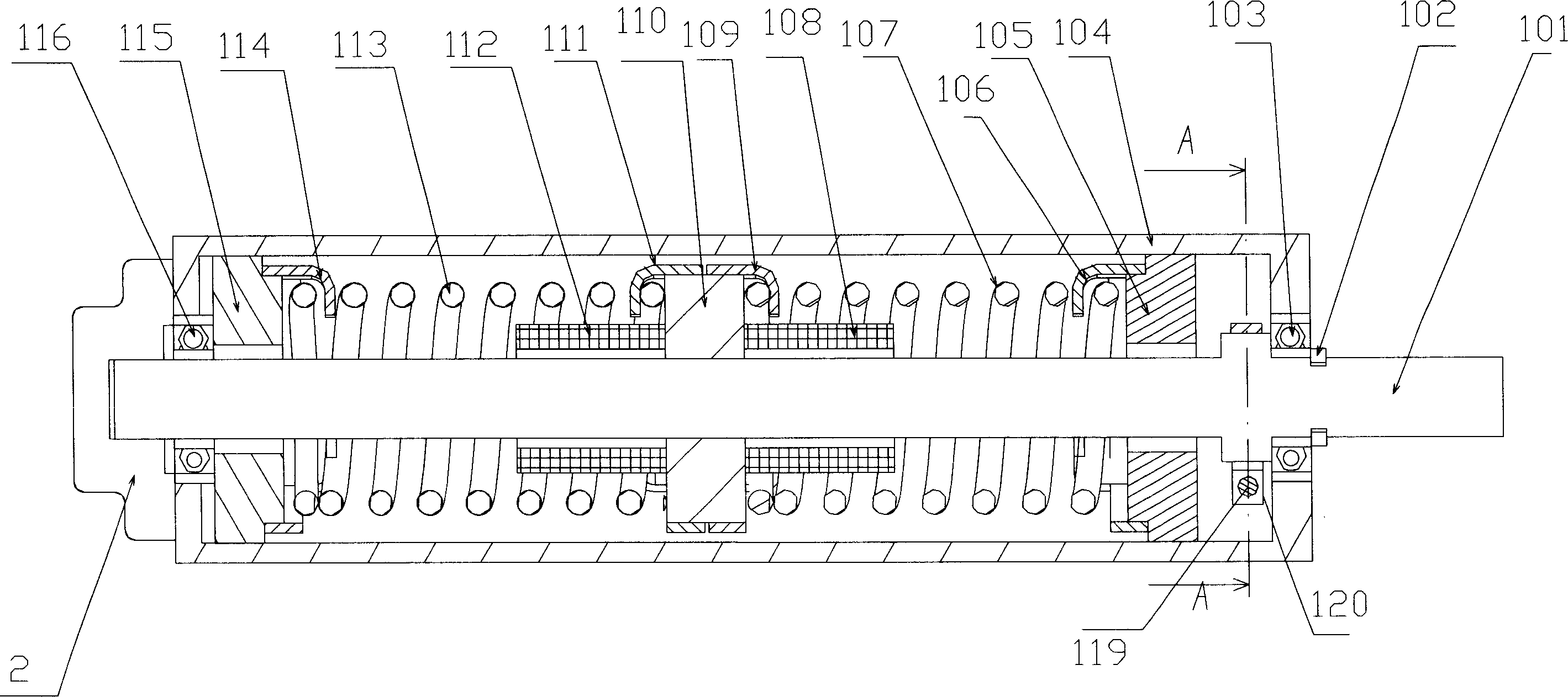
[0027] Embodiment 1. The steering resistance simulation device of the wire-by-wire steering mechanism mainly includes the following components: a steering column 101 (connected to the steering wheel), a steering resistance simulator housing 104, a first elastic member, a second elastic member, a thrust nut 110, an upper Support 105 and lower support 115. The first elastic member can be a spring, such as an extension spring or a torsion spring, or other elastic members. The first elastic member in this embodiment is an extension spring located on the opposite side of the thrust nut 110 (that is, it is generated by stretching or compressing). Elastic deformation), referred to in this embodiment as the upper end spring 107 and the lower end spring 113, and the upper end spring 107 and the lower end spring 113 have the same stiffness, length and installation parameters, the length of the elastic member refers to the elastic member in the state of no elastic deformation below the n...
Embodiment 2
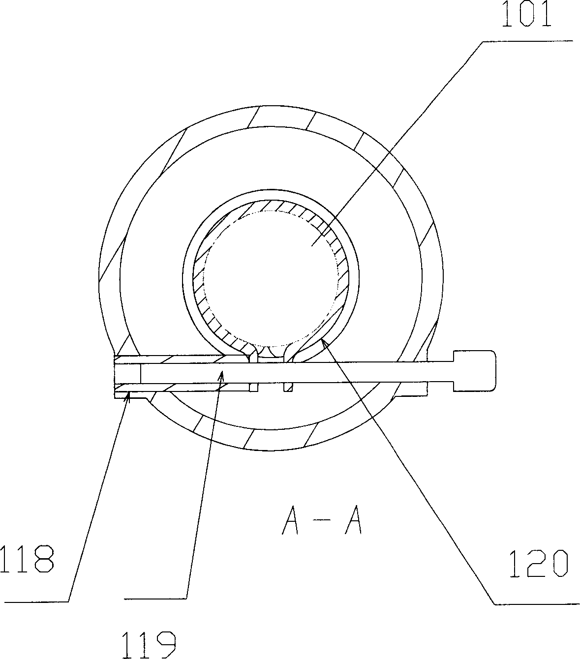
[0033] Embodiment 2. In order to make the steering wheel have a better steering "road feel" when the vehicle is turned away from the middle position, as the best embodiment of the present invention, a friction resistance elastic sleeve is added on the basis of Embodiment 1, such as figure 2 ,, 3, 4 shown. The friction resistance elastic sleeve 120 is looped on the outside of the steering column 101, and the friction resistance elastic sleeve 120 is fixed on the adjustment nut 118 ( figure 2 (not shown), the adjusting nut 118 is fixed on the housing 104 , so that the friction resistance elastic sleeve 120 is fixed on the housing 104 . Friction resistance elastic sleeve 120 is an open elastic sleeve, such as image 3 , 4 As shown, its inner wall is pasted with a friction plate 121, and there are two holes at the opening roll ear. The through hole 122 close to the adjusting nut 118 is a threaded hole 123 far away from the adjusting nut 118 , which is threaded and connected w...
Embodiment 3
[0034] Embodiment three, such as Figure 5 As shown, the difference from Embodiments 1 and 2 is that there is only one spring as the first elastic member, which is fixed on the upper side or the lower side of the thrust nut 110 , and the stretching stiffness of the spring is the same as the compression stiffness. When the steering wheel is turned, the steering resistance torque can also be generated to realize the functions of steering "road feel" and steering back.
[0035] The first elastic member in the above embodiment can also be a torsion spring, one end of the torsion spring is fixed on the casing, and the other end is fixed on the steering column, and corresponding deformation occurs with the rotation angle of the steering column to hinder the rotation of the steering column , resulting in a steering resistance torque.
PUM
 Abstract
Description
Claims
Application Information
 - R&D
- Intellectual Property
- Life Sciences
- Materials
- Tech Scout
- Unparalleled Data Quality
- Higher Quality Content
- 60% Fewer Hallucinations
Browse by: Latest US Patents, China's latest patents, Technical Efficacy Thesaurus, Application Domain, Technology Topic, Popular Technical Reports.
© 2025 PatSnap. All rights reserved.Legal|Privacy policy|Modern Slavery Act Transparency Statement|Sitemap|About US| Contact US: help@patsnap.com


