

Brad grille
A soil nailing and grid technology is applied in the fields of foundation pit support, slope protection, and foundation treatment engineering, which can solve the problems of poor reinforcement effect and shallow foundation pit support depth, and achieve the effect of remarkable effect and low reinforcement cost.
Inactive Publication Date: 2006-12-27
张继红
View PDF1 Cites 4 Cited by
- Summary
- Abstract
- Description
- Claims
- Application Information
AI Technical Summary
Problems solved by technology
[0002] Existing soil nail slope protection, soil nail wall foundation pit support methods and composite soil nail wall support methods all construct soil nails in the soil, and then connect the soil nails with the reinforced concrete on the slope to form soil nails. Wall support form, the soil nails of the existing soil nail wall support are generally arranged in parallel or approximately parallel in the soil, although in the patent application of "Soil Nail Support Method for Soft Soil Slope" (application number: CN03112359. 7) The practice of using vertical anchor rods at the excavation surface is disclosed, but because the existing soil nails do not cross in the soil, the reinforcement effect of the soil nails on the soil is relatively poor. During the protection, the suitable depth of foundation pit support is relatively shallow, which is subject to certain restrictions in engineering applications.
Method used
View moreImage
Smart ImageViewing Examples

Examples
Embodiment Construction
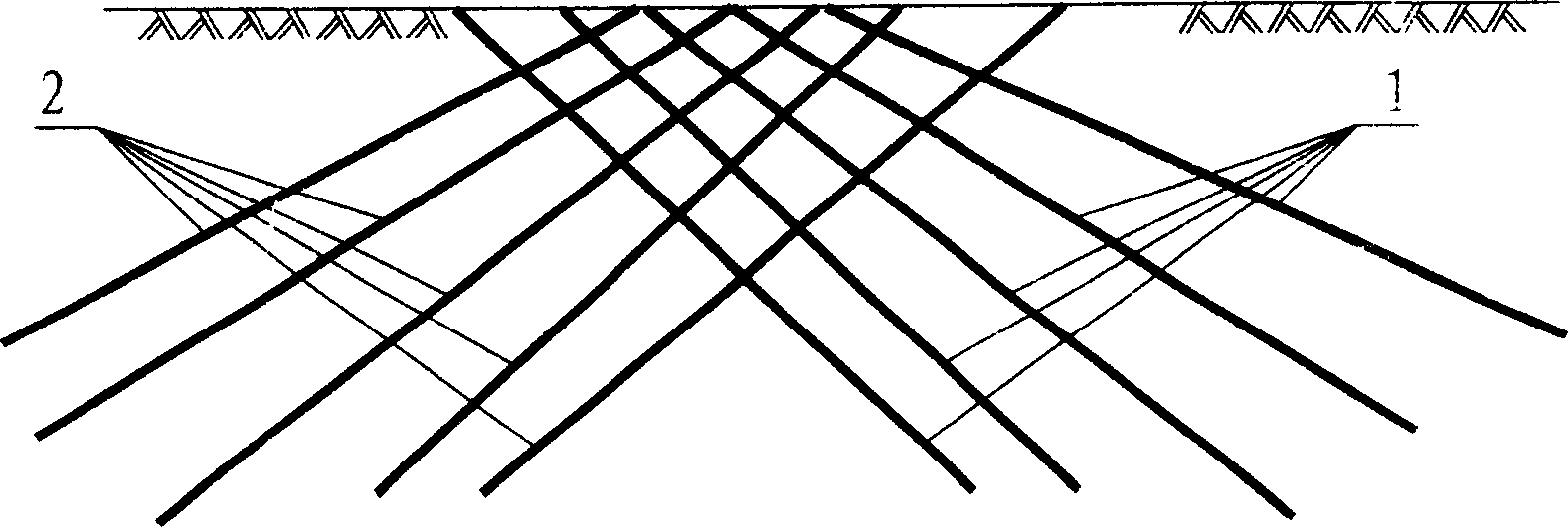
[0012] As an embodiment of the soil nail grid of the present invention, in combination with figure 1 Illustrate the specific embodiment of the present invention, can construct on the ground earlier as figure 1 The soil nail 1 shown in , and then construct the upper nail 2 interlaced with the soil nail 1, so that the soil nail 1 and the soil nail 2 are staggered into a grid shape, and the construction of the soil nail grid of the present invention is completed.
Login to View More PUM
 Abstract
The invention relates to a soil nail grid, which is formed by at least one group of soil nails in the soil. The invention uses grid soil nail and the soil to provide carrying force, to utilize the physical character of soil and soil nail; and it uses the anti-drawing strength of soil nail grid to compensate the defect as low soil anti-drawing strength, with low cost and wide application.
Description
technical field [0001] The invention relates to the field of civil engineering, in particular to slope protection, foundation pit support and foundation treatment engineering. Background technique [0002] Existing soil nail slope protection, soil nail wall foundation pit support methods and composite soil nail wall support methods all construct soil nails in the soil, and then connect the soil nails with the reinforced concrete on the slope to form soil nails. Wall support form, the soil nails of the existing soil nail wall support are generally arranged in parallel or approximately parallel in the soil, although in the patent application of "Soil Nail Support Method for Soft Soil Slope" (application number: CN03112359. 7) The practice of using vertical anchor rods at the excavation surface is disclosed, but because the existing soil nails do not cross in the soil, the reinforcement effect of the soil nails on the soil is relatively poor. During protection, the suitable de...
Claims
Login to View More Application Information
Patent Timeline
 Patent Type & Authority Applications(China)
IPC IPC(8): E02D5/74E02D17/20
Inventor 张继红
Owner 张继红