Automatic compensation controller for fluid

An automatic compensation and control device technology, applied in the direction of fluid flow, mechanical equipment, etc., can solve the problems of increasing the cost of the valve body system, maintaining or increasing the output flow, and the valve core cannot be automatically adjusted, and achieves good response, sensitive characteristics and structure. Simple, Adjustable Effects

Inactive Publication Date: 2006-12-27
高玉宗
View PDF0 Cites 8 Cited by
  • Summary
  • Abstract
  • Description
  • Claims
  • Application Information

AI Technical Summary

Problems solved by technology

[0003] However, this control method inevitably has the disadvantages of low control efficiency and poor control effect.
First of all, because it relies entirely on the external driving force to control the movement of the spool, the spool itself cannot automatically adjust with changes in fluid parameters, so the existing valve technology cannot quickly adjust itself according to real-time changes in fluid parameters; secondly , the existing valve technology without exception is a valve body that only has the function of adjusting one fluid parameter, such as a pressure regulating valve and a speed regulating valve. In practical applications, the fluid parameters at both ends of the flow channel, For example, the pressure, flow rate or flow may change very complicated at the same time. In such a complex working environment, it is difficult for

Method used


Image

  • Automatic compensation controller for fluid
  • Automatic compensation controller for fluid
  • Automatic compensation controller for fluid

Examples


Example Embodiment

[0032] The present invention will be further described below in conjunction with specific embodiments.

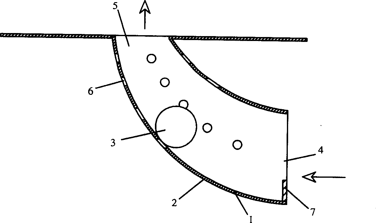
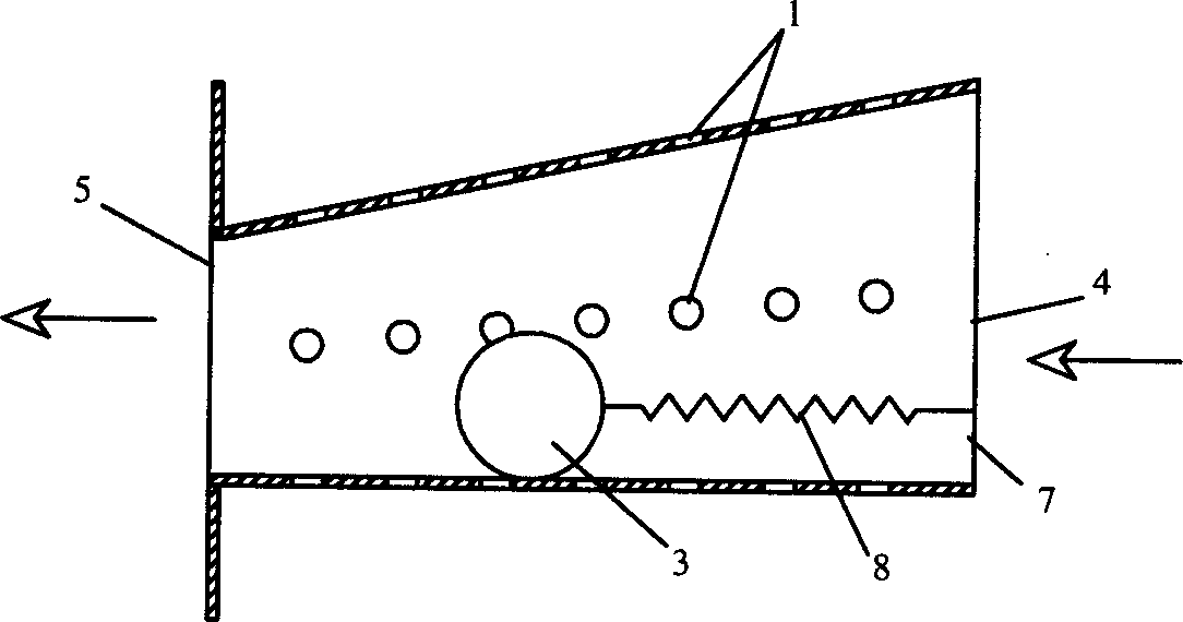
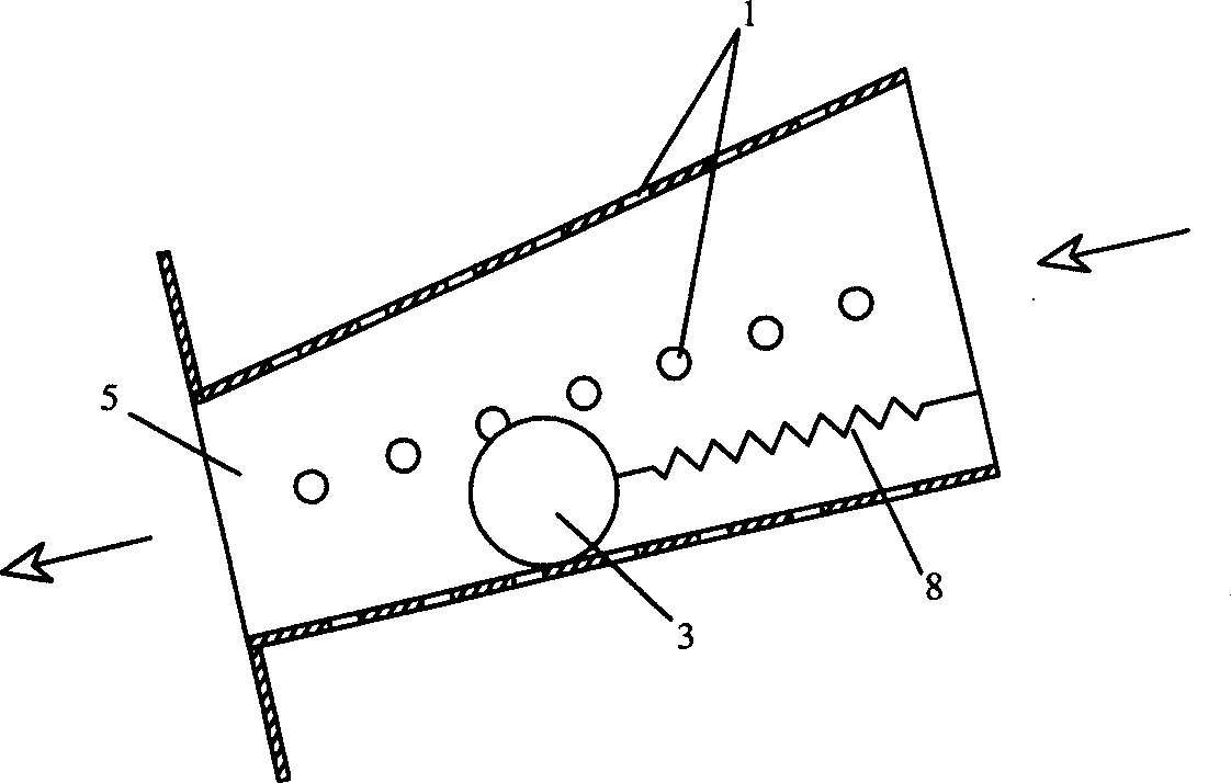
[0033] Such as figure 1 Shown is a schematic structural diagram of an embodiment of the present invention.

[0034] The flow channel 1 is a horn-shaped elbow structure with an inlet 4 at one end and an outlet 5 at the other end. Regulating holes 6 are evenly arranged around the wall of the flow channel 1, and rollers 3 are arranged in the inner cavity of the flow channel 1. The roller 3 can roll freely along the inner cavity wall of the flow channel 1, and a baffle 7 is provided at the mouth of the inlet 4 to prevent the roller 3 from rolling off the flow channel 1.

[0035] First of all, because the flow channel 1 has a horn-shaped elbow structure with a large inlet end and a small outlet end, when the flow channel 1 is filled with fluid, the roller 3 is in a certain equilibrium position, and its own gravity and the force of the fluid Phase balance.

[0036] When the pressure...


PUM


Abstract

The invention relates to a fluid automatic compensate controller, which comprises a flow channel, wherein the invention is characterized in that: the flow channel is arranged with an adjuster that axially moves by the fluid function; the section difference between the flow channel and the adjuster changes with the motion of adjuster; the adjuster will generate function force balanced with fluid force in the moving process. The invention has simple structure, wide application and sensitive control. The invention can control the speed, pressure and flux of output fluid quickly.

Description

technical field [0001] The invention relates to the field of fluid control, in particular to a fluid control device that can automatically compensate and adjust with changes in fluid parameters at an input end and an output end. Background technique [0002] Traditional fluid control technology mainly relies on various valve bodies to control and adjust various fluid parameters, and its control methods are mainly divided into two types: manual control and electric control. Its working principle is to rely on external force to change the position of the spool to adjust the effective area of ​​the fluid passing through the valve body, so as to achieve the purpose of changing the fluid parameters such as the pressure or flow rate or flow rate of the output fluid. [0003] However, this control method inevitably has the disadvantages of low control efficiency and poor control effect. First of all, because it relies entirely on the external driving force to control the movement ...

Claims


Application Information

Patent Timeline
IPC IPC(8): F15D1/02
Inventor 高玉宗
Owner 高玉宗
Why Eureka
Try Eureka