Inversed-F type antenna
An antenna and metal sheet technology, applied in the resonant antenna, radiating element structure and other directions, can solve the problems of efficiency loss, increase the complexity of the antenna, and insufficient to meet the
- Summary
- Abstract
- Description
- Claims
- Application Information
AI Technical Summary
Problems solved by technology
Method used
Image

Examples
Embodiment 3
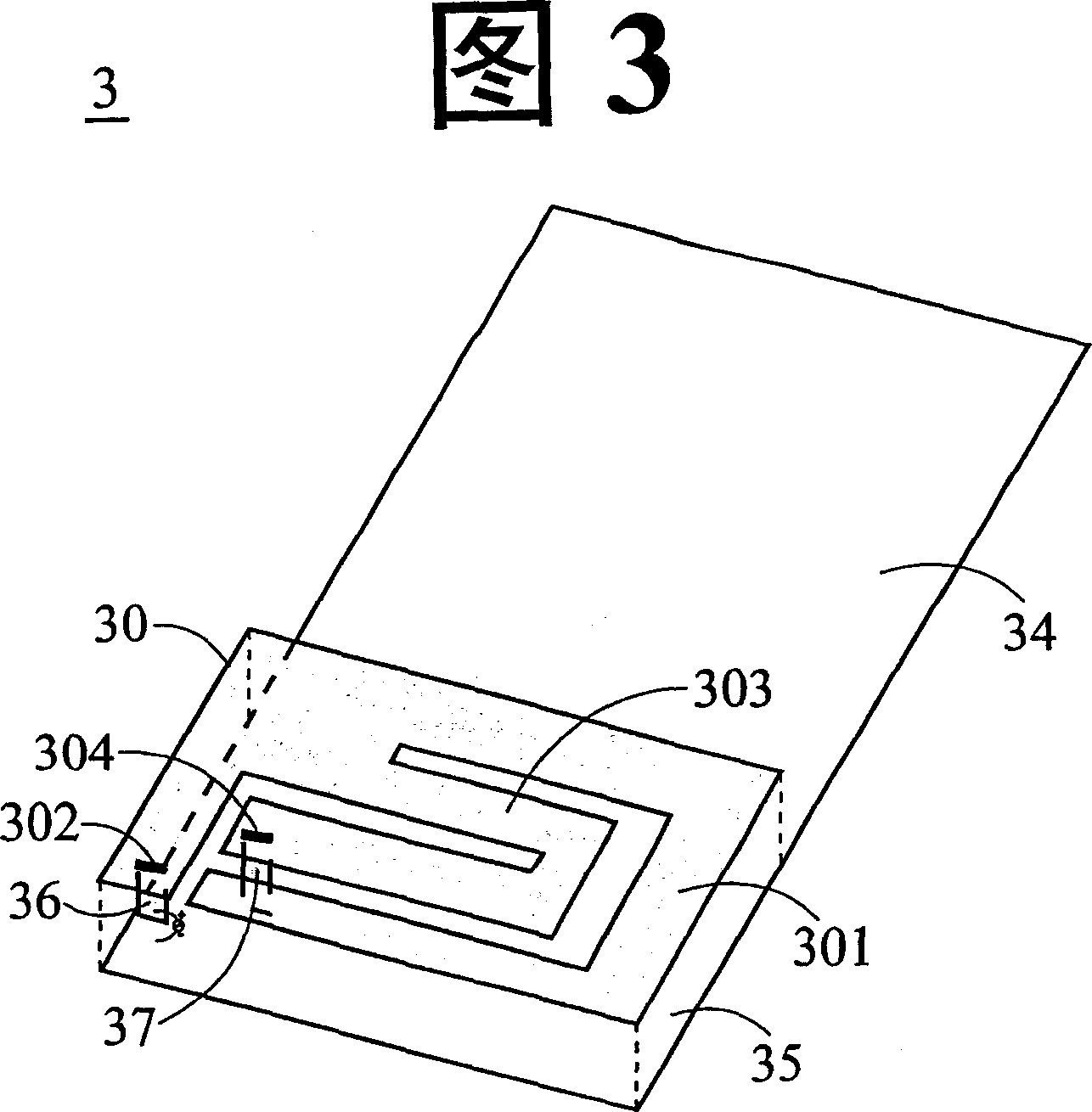
[0029] FIG. 3 shows an embodiment 3 of the inverted-F antenna of the present invention, which includes: a radiating metal sheet 30 having a first sub-radiating metal sheet 301, a feeding point 302, and a The second sub-radiation metal sheet 303 and a short-circuit point 304; a ground plane 34, a dielectric substrate 35, a feed-in metal sheet 36 and a short-circuit metal sheet 37. One of the first sub-radiating metal sheets 301 has a starting end and an end. The starting end is located at an edge of the radiating metal sheet, and the end extends in a spiral manner to form a first path, and the end is close to the starting end And is an open circuit; the feeding point 302 is located near the starting end of the first sub-radiating metal sheet; the second sub-radiating metal sheet 303 has a starting end and an end, wherein the starting end and the first sub-radiating metal sheet The start end of 30 is connected, and the end extends along the inner edge of the first sub-radiating meta...
Embodiment 5
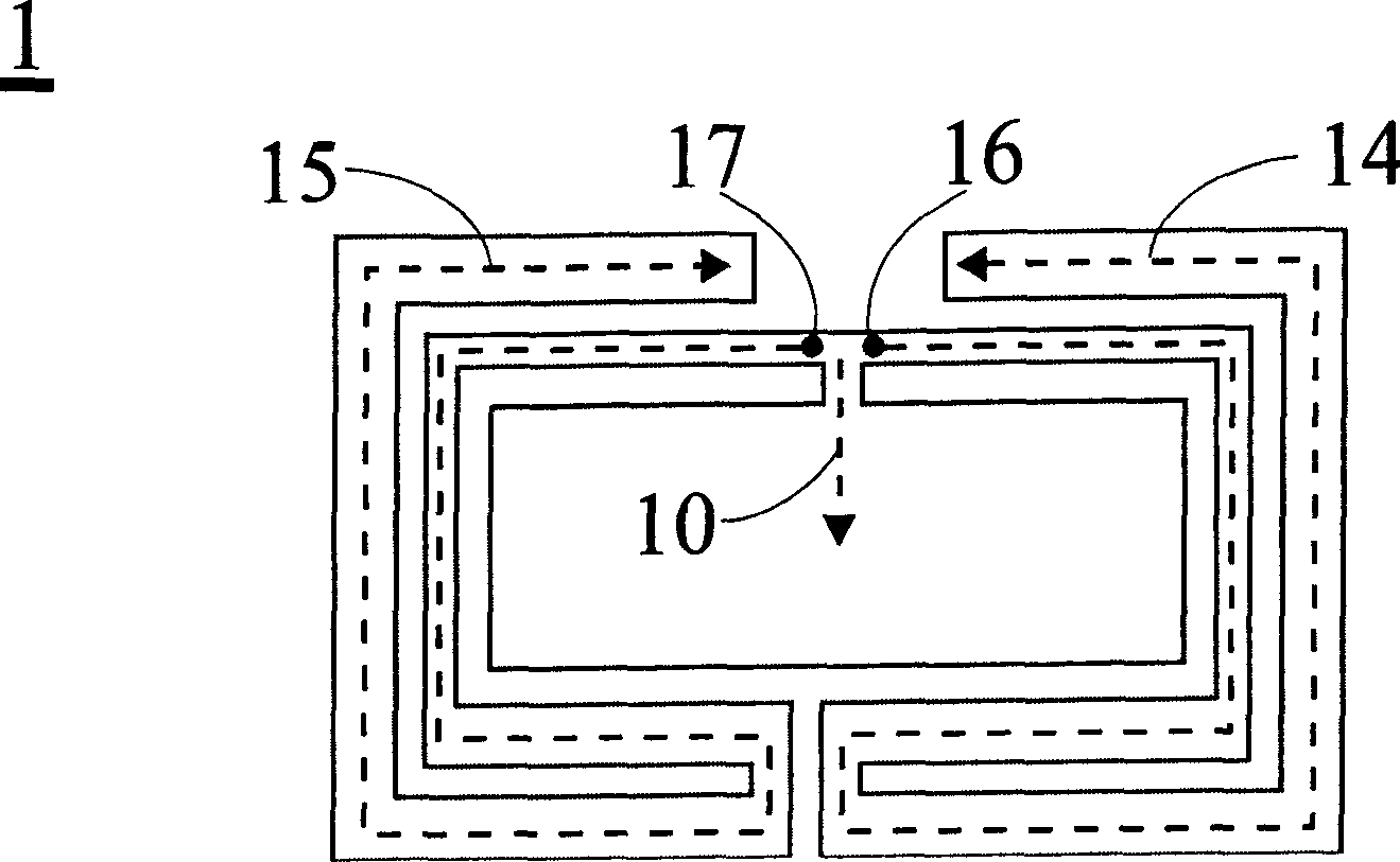
[0032] Fig. 5 shows another embodiment 5 of the inverted-F antenna of the present invention, which includes: a radiating metal sheet 50 having a first sub-radiating metal sheet 501, a feeding point 502, A second sub-radiation metal sheet 503 and a short-circuit point 504, a ground plane 54, a dielectric substrate 55, a feed-in metal sheet 56 and a short-circuit metal sheet 57. The first sub-radiating metal sheet 501 and the second sub-radiating metal sheet 503 respectively extend in a spiral manner to form a first and a second path for generating the first (low frequency) and second (low frequency) of the antenna, respectively. (Sub-high frequency) and third (high frequency) operating modes, where the second path is surrounded by the first path, and the feed point 502 and the short-circuit point 504 are respectively located in the first sub-radiating metal sheet The starting end of 501 and the end of the second sub-radiating metal sheet 503, the first sub-radiating metal sheet 501...
Embodiment 6
[0033] Fig. 6 shows another embodiment 6 of the inverted-F antenna of the present invention, which includes: a radiating metal sheet 60 having a first sub-radiating metal sheet 601, a feeding point 602, A second sub-radiation metal sheet 603 and a short-circuit point 604, a ground plane 64, a dielectric substrate 65, a feed-in metal sheet 66 and a short-circuit metal sheet 67. The first sub-radiating metal sheet 601 and the second sub-radiating metal sheet 603 respectively extend in a spiral manner to form a first and a second path for generating the first (low frequency) and second (low frequency) of the antenna, respectively. (Sub-high frequency) and third (high frequency) operating modes, where the second path is surrounded by the first path, and the feed point 602 and the short-circuit point 604 are respectively located in the first sub-radiating metal sheet The start end of 601 and the end of the second sub-radiation metal sheet 603. The second sub-radiation metal sheet 603 o...
PUM
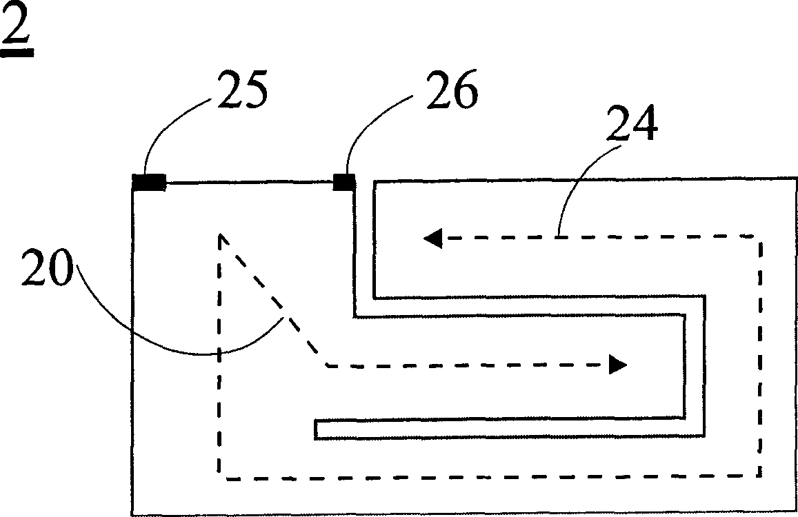
 Abstract
Description
Claims
Application Information
 - Generate Ideas
- Intellectual Property
- Life Sciences
- Materials
- Tech Scout
- Unparalleled Data Quality
- Higher Quality Content
- 60% Fewer Hallucinations
Browse by: Latest US Patents, China's latest patents, Technical Efficacy Thesaurus, Application Domain, Technology Topic, Popular Technical Reports.
© 2025 PatSnap. All rights reserved.Legal|Privacy policy|Modern Slavery Act Transparency Statement|Sitemap|About US| Contact US: help@patsnap.com