
Imaging system

An imaging system and image technology, which is applied to the components of the TV system, image communication, TV, etc., can solve problems such as unnatural borders, and achieve the effect of improving image processing time

Inactive Publication Date: 2006-12-27
NILES PARTS CO LTD
View PDF1 Cites 7 Cited by
  • Summary
  • Abstract
  • Description
  • Claims
  • Application Information

AI Technical Summary

Problems solved by technology

Thus, this prior art can reduce the flicker inherent in double exposure control, but it causes the problem of creating unnatural borders in the combined full image and memory image

Method used


Image

  • Imaging system
  • Imaging system
  • Imaging system

Examples


no. 1 example

[0127] According to the first embodiment, the following analysis Figure 17 Image:

[0128] The number of gray blocks around the big billboard in the upper center of the image is 0;

[0129] The number of gray blocks around the small billboard on the left of the image is 0;

[0130] The number of gray blocks around the taillights of the vehicle ahead in the center of the image is 2;

[0131] The number of gray blocks around the street light on the upper right of the image is 4; and

[0132] The number of gray blocks around the headlights of oncoming vehicles in the lower right corner of the image is 32.

[0133] Next, 32 is Figure 17 The maximum number of gray blocks in the image, so choose it as the degree of halo.

[0134] That is, the number of gray blocks around the headlights of oncoming vehicles 32 is Figure 17 The degree of halo of the image.

[0135] The second method of calculating the degree of halation based on the size and probability of the white block group will be...


PUM


Abstract

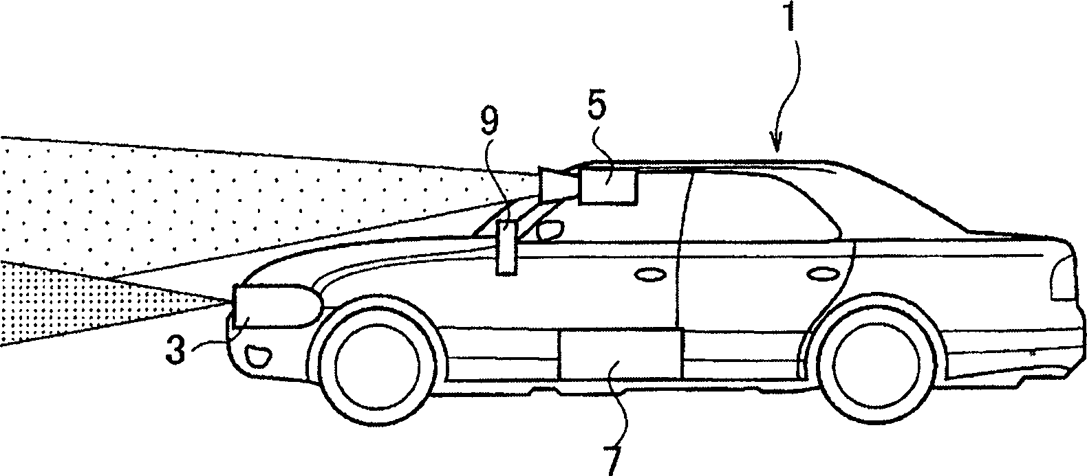
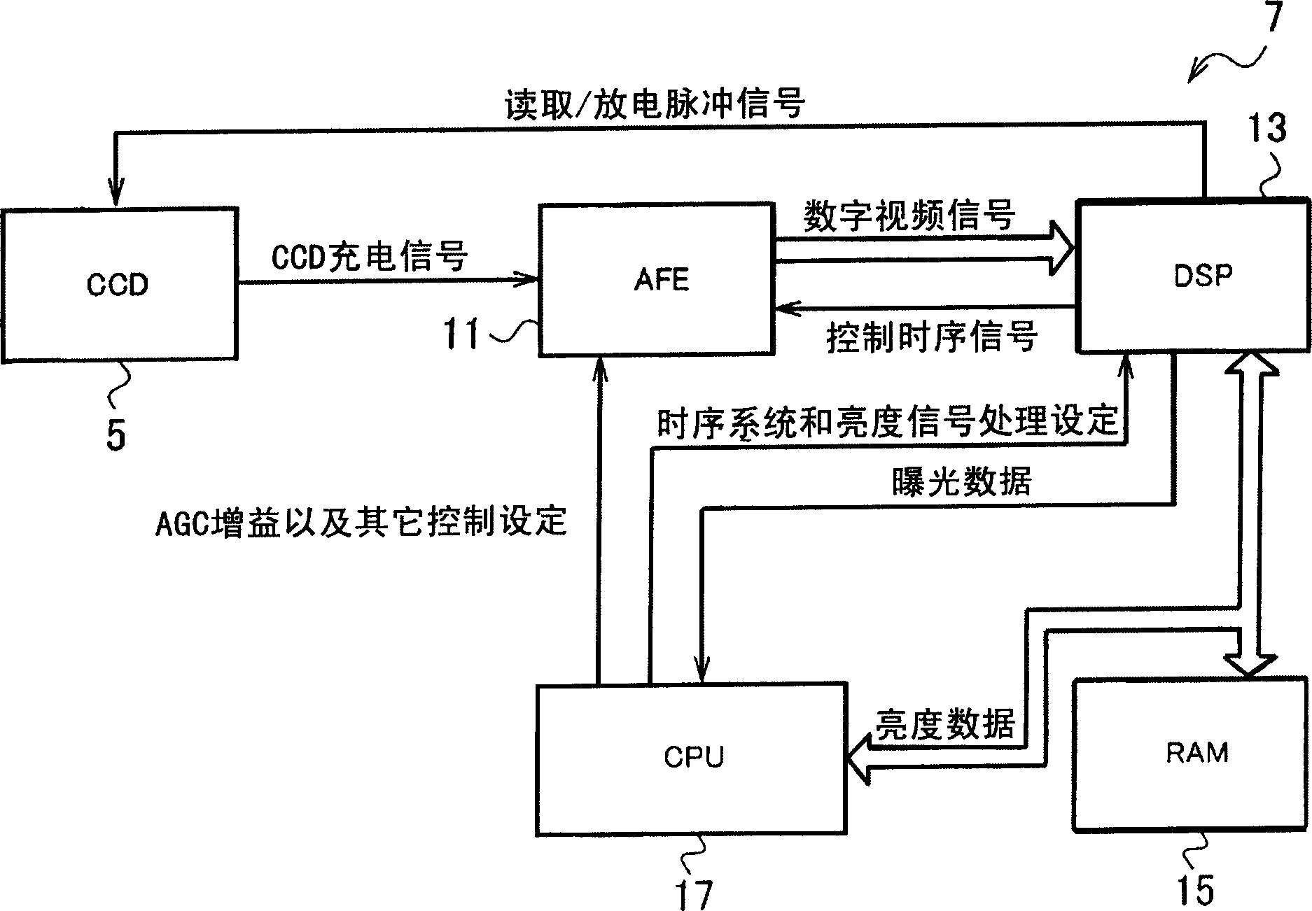
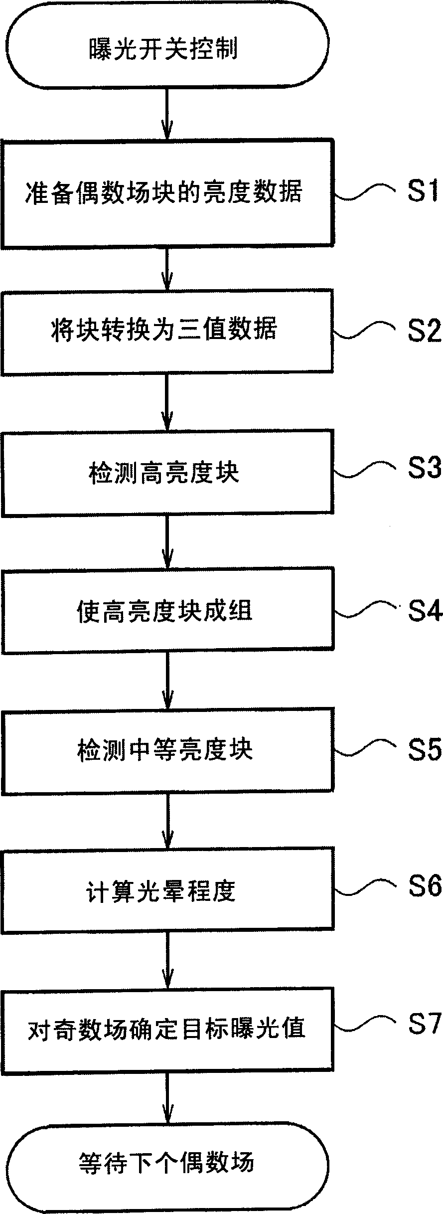
An imaging system comprises an IR lamp irradiating infrared light, a CCD camera (5) for imaging a place irradiated by the IR lamp and converting the image into an electric signal, and an image processing unit (7) capable of continuously and periodically outputting images of different exposure amounts by varying the signal storage time of the CCD camera (5) at a specified period. The image processing unit (7) extracts a mass of high luminance having a spread of intermediate luminance on the periphery of the images outputted periodically on one hand, and controls the signal storage time of the images periodically outputted according to the extent of the mass of high luminance on the other hand.

Description

Technical field [0001] The present invention relates to an imaging system using, for example, a CCD camera. Background technique [0002] Figure 22 An imaging system according to the prior art is shown. in Figure 22 Here, the imaging system includes a CCD (Charge Coupled Device) 101 as an image acquisition unit, a DSP (Digital Signal Processor) 103 as an image processing unit, and a CPU (Central Processing Unit) 105. [0003] The CPU 105 and the DSP 103 are connected to each other through the multiplexer 107. The CPU 105 receives a signal from the shutter speed setting switch 109. The switch 109 sets the shutter speed for odd fields and sets the shutter speed for even fields. [0004] The CPU 105 reads the shutter speed set by the switch 109, encodes the read shutter speed for a given field, and provides the encoded shutter speed. DSP 103 output Figure 23 The field pulse signal shown. When the field pulse signal is high, the multiplexer 107 supplies the shutter speed set for ...

Claims


Application Information

Patent Timeline
Patent Type & Authority Applications(China)
IPC IPC(8): H04N5/235H04N5/335H04N5/232H04N5/238H04N5/345H04N5/353H04N5/359H04N5/372H04N5/378
CPCH04N5/2354H04N5/2352H04N23/72H04N23/74
Inventor 河村弘之星野弘典
Owner NILES PARTS CO LTD
Learn More