Supercharge Your Innovation With Domain-Expert AI Agents!

Lift dragging and driving device

A transmission device and traction technology, which is applied in the field of traction transmission devices, can solve problems such as high cost and troublesome civil construction of buildings, and achieve the effect of convenient civil construction and reduced occupied space

Active Publication Date: 2007-01-03
CANNY ELEVATOR
View PDF0 Cites 0 Cited by
  • Summary
  • Abstract
  • Description
  • Claims
  • Application Information

AI Technical Summary

Problems solved by technology

The rear side of the car needs to be equipped with a load-bearing wall, which is used to fix the control box of the elevator and the running guide rail of the car. Since the counterweight and the traction motor are located Build a load-bearing wall on the side to install the traction motor and the running guide rail of the counterweight, which makes the civil construction of the building more troublesome, especially for small buildings (such as residential buildings), it is difficult to leave space on both sides of the car And build a load-bearing wall, and building a load-bearing wall around the elevator shaft will make the cost high

Method used


Image

  • Lift dragging and driving device
  • Lift dragging and driving device
  • Lift dragging and driving device

Examples


Embodiment Construction

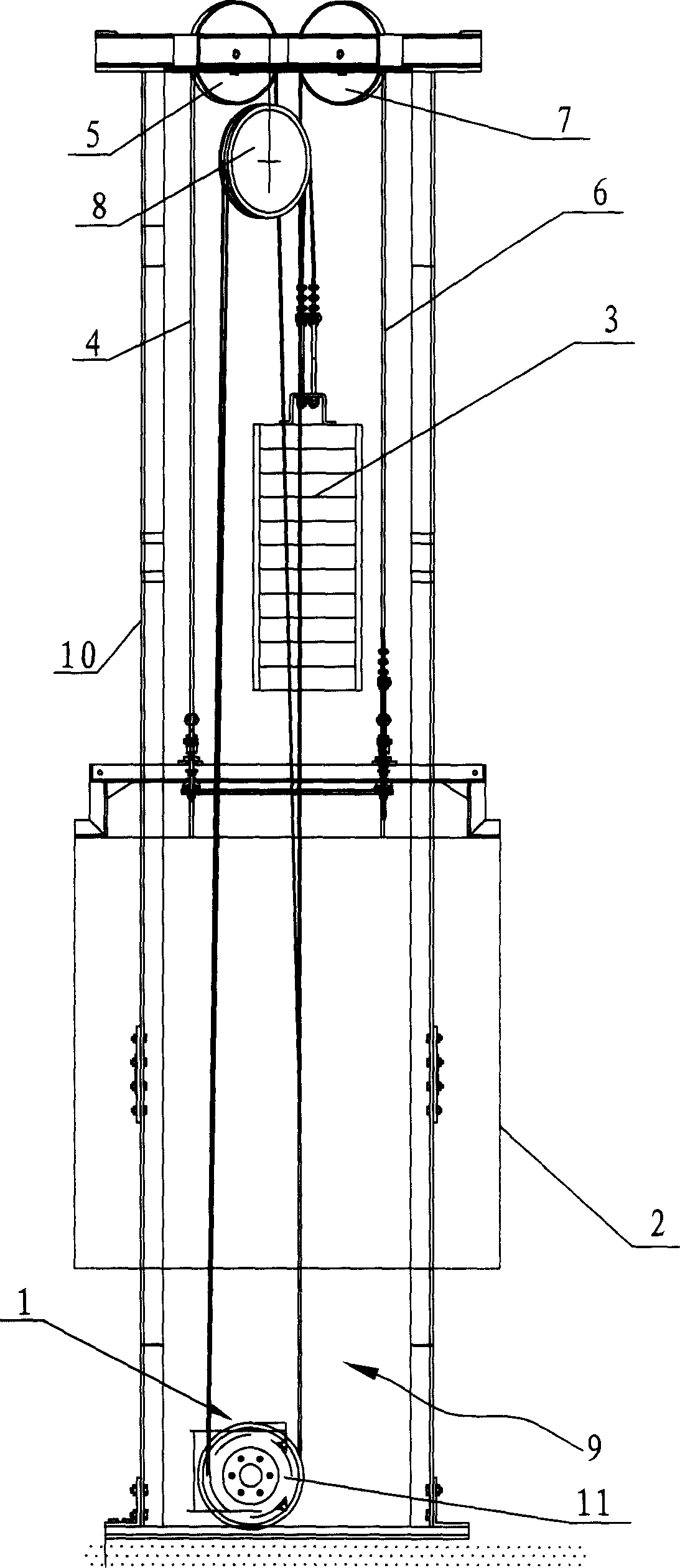
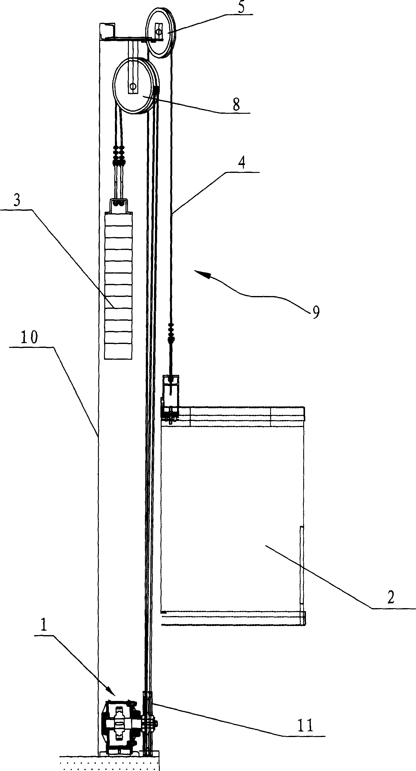
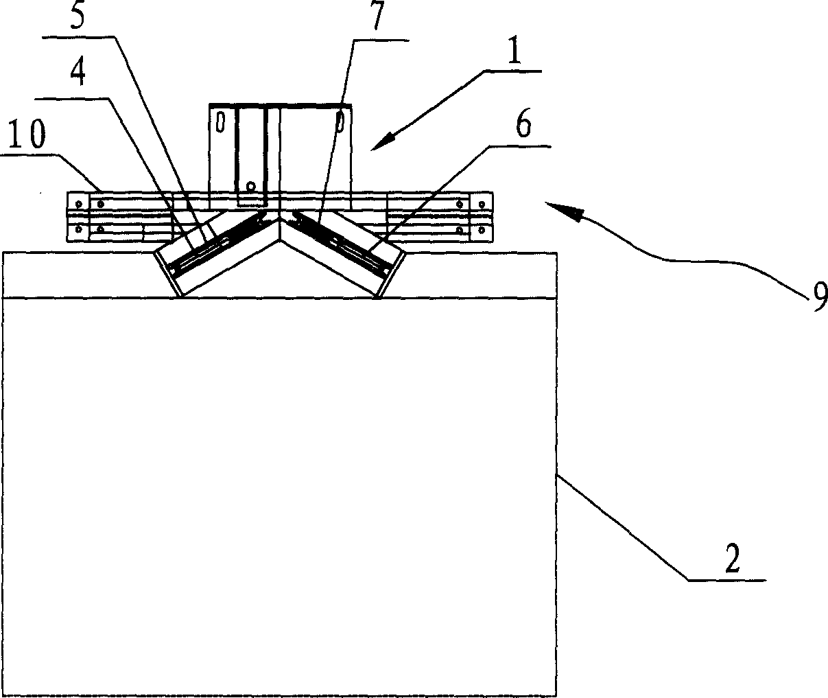
[0011] See attached figure 1 one attached image 3 As shown, a traction transmission device for an elevator includes a traction motor 1, a car 2 that is drive-connected to the output shaft of the traction motor 1 through a traction mechanism 9, and the traction mechanism 9 includes at least one pulley, attached figure 1 In the illustrated embodiment, there are three pulleys, including a first pulley 5, a second pulley 7, and a third pulley 8. The first pulley 5 is wound with a first traction rope 4, and the second pulley 7 is wound with a There is a second traction rope 6, one end of the first traction rope 4 and the second traction rope 6 are respectively connected to the top of the car 2, and the connection points are two symmetrical points, which help to keep the car 2 under The force is balanced and uniform; the rotor of the traction motor 1 is coaxially fixedly connected with an output turntable 11, and the first traction rope 4 and the second traction rope 6 respective...


PUM


Abstract

The lift dragging and driving mechanism includes one dragging motor, one cage connected via a dragging mechanism to the dragging motor, and one output turntable connected to the rotor of the motor. The dragging mechanism includes one dragging rope wound on the output turntable, at least one pulley for the dragging rope to wind around, and one counterweight block. One end of the dragging rope is connected to the cage and the other end of the dragging rope is connected to the counterweight block. The dragging motor and the dragging mechanism are set behind the back wall of the cage, so that bearing wall is needed only for the back of the cage, and this results in convenient civil construction and reduced space the lift block occupies.

Description

technical field [0001] The invention relates to a traction transmission device of an elevator. Background technique [0002] In the prior art, the traction transmission device of the elevator includes a traction motor and a traction mechanism driven by the traction motor. The traction mechanism includes a pulley block and a traction rope. One end of the traction rope is connected to the car, and the other end of the traction rope One end is connected to the counterweight, and the movement of the traction rope is controlled by the traction motor. The counterweight and traction motor are arranged on the side of the car, and the pulley block is located on the top of the hoistway, and the traction rope goes around the top of the car. The pulley block is fixedly connected with the car, and the traction motor drives the traction rope to move after starting to realize the lifting movement of the car, and the counterweight moves in the opposite direction to...

Claims


Application Information

Patent Timeline
IPC IPC(8): B66B11/04
Inventor 王友林李军
Owner CANNY ELEVATOR
Features
  • R&D
  • Intellectual Property
  • Life Sciences
  • Materials
  • Tech Scout
  • Unparalleled Data Quality
  • Higher Quality Content
  • 60% Fewer Hallucinations
Learn More