Single bus design method for space application optical fiber gyroscope assembly

A fiber optic gyroscope and a design method technology, applied in Sagnac effect gyroscopes and other directions, can solve the problems of weight and reliability reduction, and achieve the effects of improving reliability, strong interchangeability, and easy redundant design

Inactive Publication Date: 2007-01-03
BEIHANG UNIV
View PDF0 Cites 0 Cited by
  • Summary
  • Abstract
  • Description
  • Claims
  • Application Information

AI Technical Summary

Problems solved by technology

The existing 3 fiber optic gyroscopes have a multi-bus structure, that is, the 3 fiber optic gyroscopes are connected to the electrical system through 3 data buses, so that the weight and reliability of the system are relatively reduced

Method used


Image

  • Single bus design method for space application optical fiber gyroscope assembly
  • Single bus design method for space application optical fiber gyroscope assembly
  • Single bus design method for space application optical fiber gyroscope assembly

Examples


Embodiment Construction

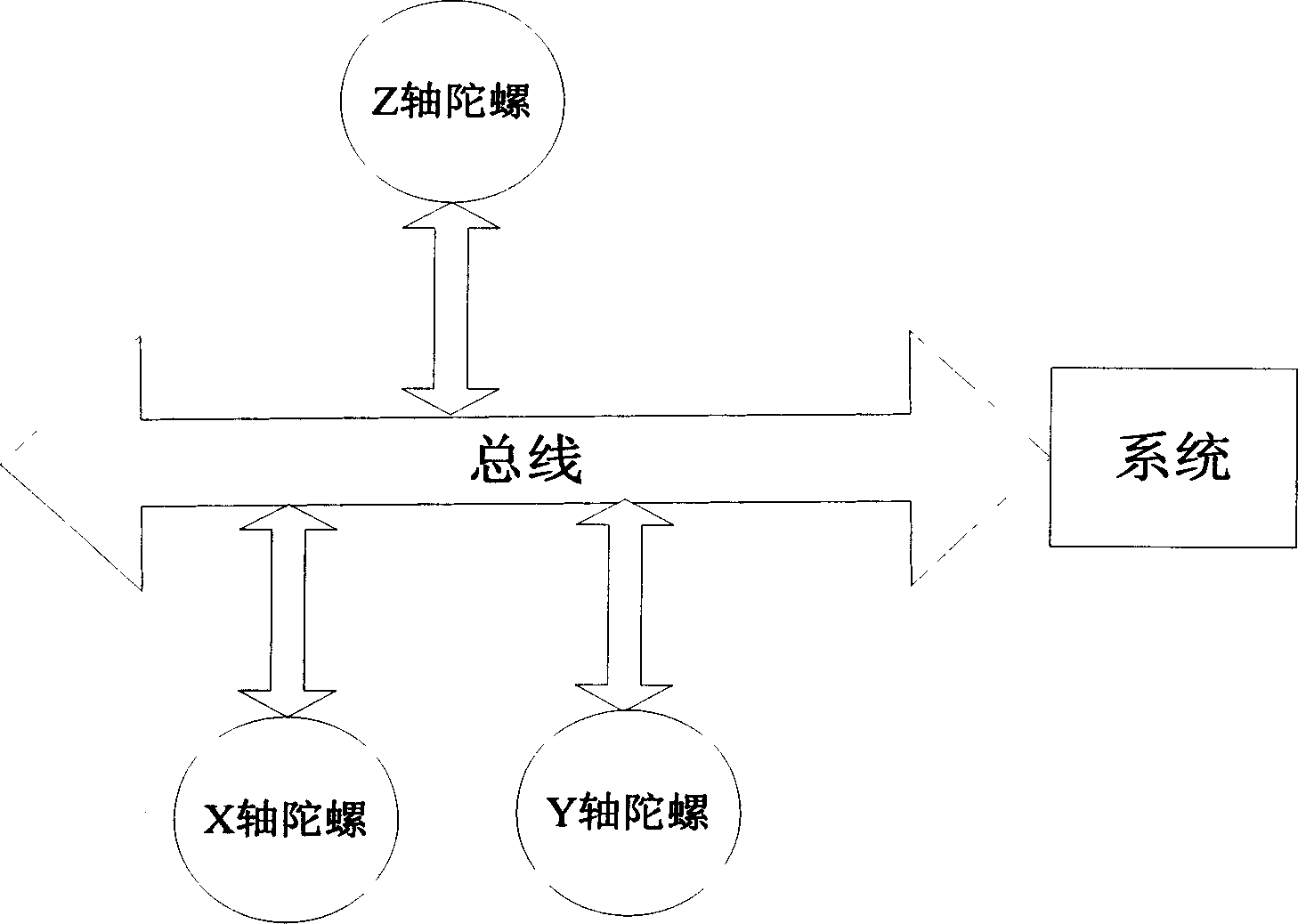
[0012] Such as figure 1 As shown, the x-axis gyro, y-axis gyro, and z-axis gyro are respectively connected to the bus and connected to the system through the bus. The receiving data lines of the 3 gyroscopes are hung on a bus and connected with the system sending data lines, and the sending data lines of the 3 gyroscopes are hung on a bus and connected with the system receiving data lines. The identification codes of 3 gyroscopes are agreed in advance, and the system sends an identification code to the 3 gyroscopes at the same time. The gyroscopes with matching identification codes occupy the bus and send data to the system, and release the bus after sending data. The identification codes of the x-, y-, and z-axis gyroscopes in the present invention are B1000104, C2000104, and D3000104 respectively.

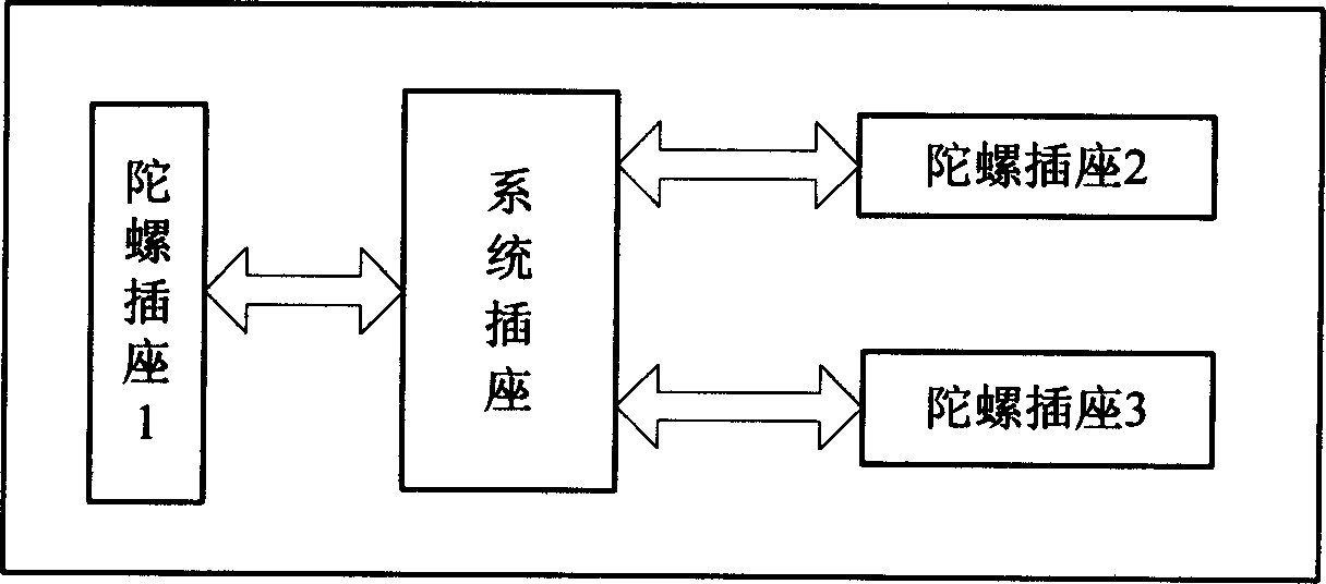
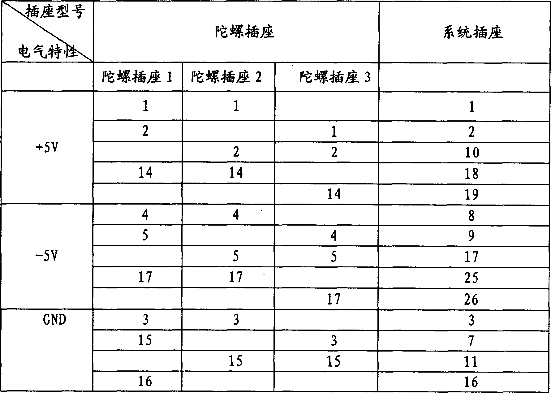
[0013] The three gyroscopes use three independent interfaces respectively, and the three gyro interface sockets, namely gyro socket 1, gyro socket 2 and gyro socket 3 use J30-25...


PUM


Abstract

A single bus design method uses for space applied optical fiber peg-top combination. System circuit connects with peg-top interface by bus; the line for accepting data of the three peg-tops connects with system sending datum line by single bus, and the line for sending data of the three peg-tops connects with system sending datum line by one bus. System connects with peg-top by principal and subordinate tape communication method and the system is the master side. It promises identification codes of three peg-tops in advance and sends one identification code to them at the same time. The peg-tops with correlative identification code take up the bus and send data to system and release the bus after sending the data. It passes data easy, quickly and true, and selects the wanted information according to the need of system. Each peg-top can debug alone and it improves the dependability and lightens weight.

Description

technical field [0001] The invention relates to an interface design for space application of an optical fiber gyroscope, in particular to a single-bus design method for a space application optical fiber gyroscope combination. Background technique [0002] In recent years, fiber optic gyroscope (FOG) has attracted much attention due to its potential advantages and application prospects, and has become the dominant device in the new generation of inertial guidance and measurement systems. With the in-depth study of fiber optic gyroscopes, various key problems of fiber optic gyroscopes have been gradually solved, and the performance of fiber optic gyroscopes has been continuously improved. Now the fiber optic gyroscope has been integrated and digitized. The zero drift of the fiber optic gyroscope developed abroad has reached within 0.001° / h, the stability of the calibration factor is better than several ppm, and the measurement accuracy has reached 0.0003° / h. The fiber optic ...

Claims


Application Information

Patent Timeline
IPC IPC(8): G01C19/72
Inventor 肖文伊小素刘德文韩艳玲李瑞刘洋
Owner BEIHANG UNIV
Why Eureka
Try Eureka