
Detection repairing system

A repair system and a technology to be tested, which is applied in the direction of measuring devices, instruments, electrical components, etc., can solve the problems of cost consumption, inability to judge the short circuit of two electrodes, etc., and achieve the effect of reducing errors and waste of human resources

Inactive Publication Date: 2007-01-03
RITDISPLAY
View PDF0 Cites 5 Cited by
  • Summary
  • Abstract
  • Description
  • Claims
  • Application Information

AI Technical Summary

Problems solved by technology

However, in the existing detection method, the defect of the organic light-emitting device is inspected by using an optical microscope in a scanning manner. This method cannot determine whether the inspected defect will cause a short circuit between the two electrodes, so all inspections must be performed during the repair stage. In other words, if all the existing defects are scanned, positioned, re-scanned, re-located, and repaired one by one with the existing technology, it will cause a lot of cost in the manufacturing process.

Method used


Image

  • Detection repairing system
  • Detection repairing system
  • Detection repairing system

Examples


Embodiment Construction

[0047] The inspection and repair system according to the preferred embodiment of the present invention will be described below with reference to the relevant drawings, wherein the same elements will be described with the same reference symbols. It should be explained here again that the organic light-emitting device described in this embodiment includes an organic light-emitting panel and an organic light-emitting element.

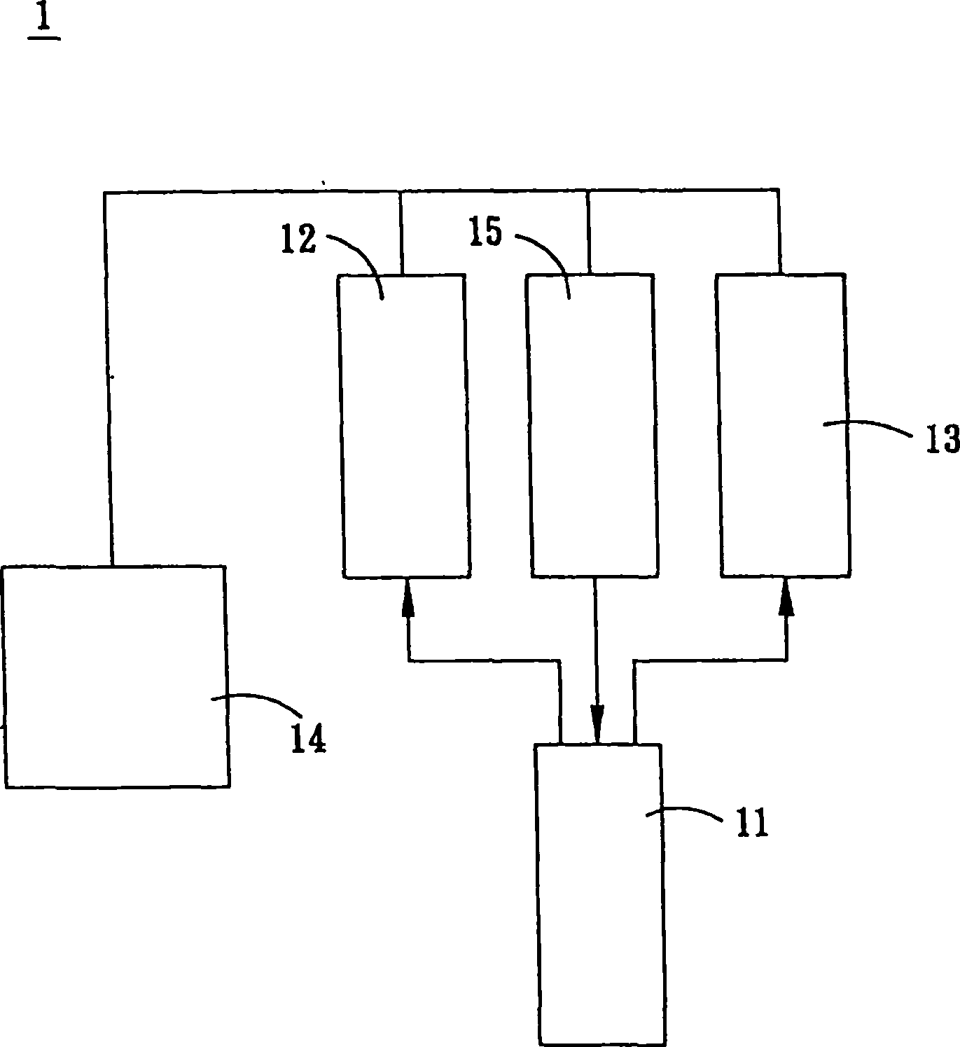
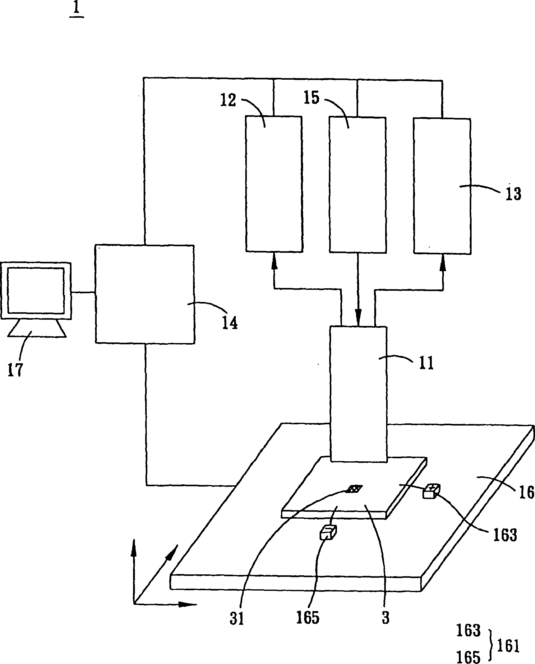
[0048] Such as figure 1 and figure 2 As shown, the inspection and repair system 1 of the present invention includes a microscope 11 , an image capture device 12 , a current detector 13 , a controller 14 , and an energy beam generator 15 .

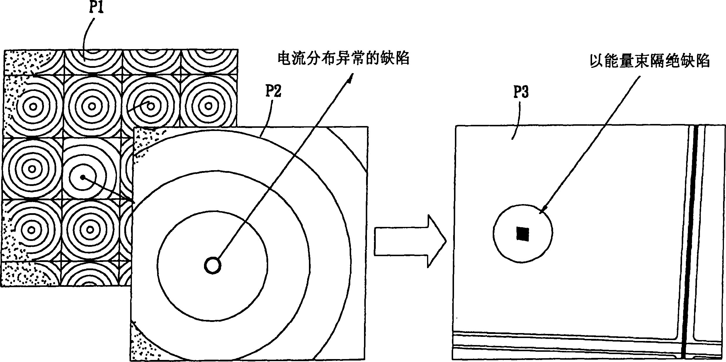
[0049] The microscope 11 is used to magnify a region to be detected of an organic light emitting device 3 . The image picker 12 is connected with the microscope 11, and captures the area image enlarged by the microscope 11 (such as image 3 As shown in P1), in this embodiment, the image capture device 12 can be an ima...


PUM


Abstract

A detecting and repairing unit is featured as exerting a bias on region to be detected at organic luminous unit when defect position is detected by detecting and repairing unit and utilizing a current detector to defect out defective position with current being distributed abnormally, using an energy beam generator to generate an energy beam being used to isolate defective position.

Description

technical field [0001] The invention relates to a detection and repair system, in particular to a detection and repair system for detecting and repairing a defect of an organic light-emitting device. Background technique [0002] The information and communication industry has become the mainstream industry today, especially portable communication and display products are the focus of development. And since the flat panel display is a communication interface between people and information, its development is particularly important. Technologies currently used in flat panel displays include Plasma Display Panel (PDP), Liquid Crystal Display (LCD), Inorganic Electroluminescence Display (ELD), Light Emitting Diode (LED) display, vacuum fluorescent display (Vacuum Fluorescence Display, VFD), field emission display (Field Emission Display, FED), and electrochromic display (Electro-Chromic Display), etc. [0003] Compared with other flat-panel displays, organic light-emitting pan...

Claims


Application Information

Patent Timeline
Patent Type & Authority Applications(China)
IPC IPC(8): H05B33/10G01N21/956G09G3/30
Inventor 廖孟傑陈济中
Owner RITDISPLAY
Learn More