Thermodynamic cycle and device

A thermodynamic cycle and pressure technology, applied in steam engine installations, machines/engines, mechanical equipment, etc., can solve problems such as low thermal efficiency, energy waste, energy crisis, etc., and achieve the effect of high thermal efficiency

Inactive Publication Date: 2007-01-10
陈培豪
View PDF0 Cites 13 Cited by
  • Summary
  • Abstract
  • Description
  • Claims
  • Application Information

AI Technical Summary

Problems solved by technology

Due to theoretical limitations, these thermal cycles and thermal devices using these thermal cycles have the disadvantage of low thermal efficiency, which directly causes a large amount of energy waste, and indirectly causes the current serious environmental pollution and energy crisis.

Method used


Image

  • Thermodynamic cycle and device
  • Thermodynamic cycle and device
  • Thermodynamic cycle and device

Examples


Embodiment 1

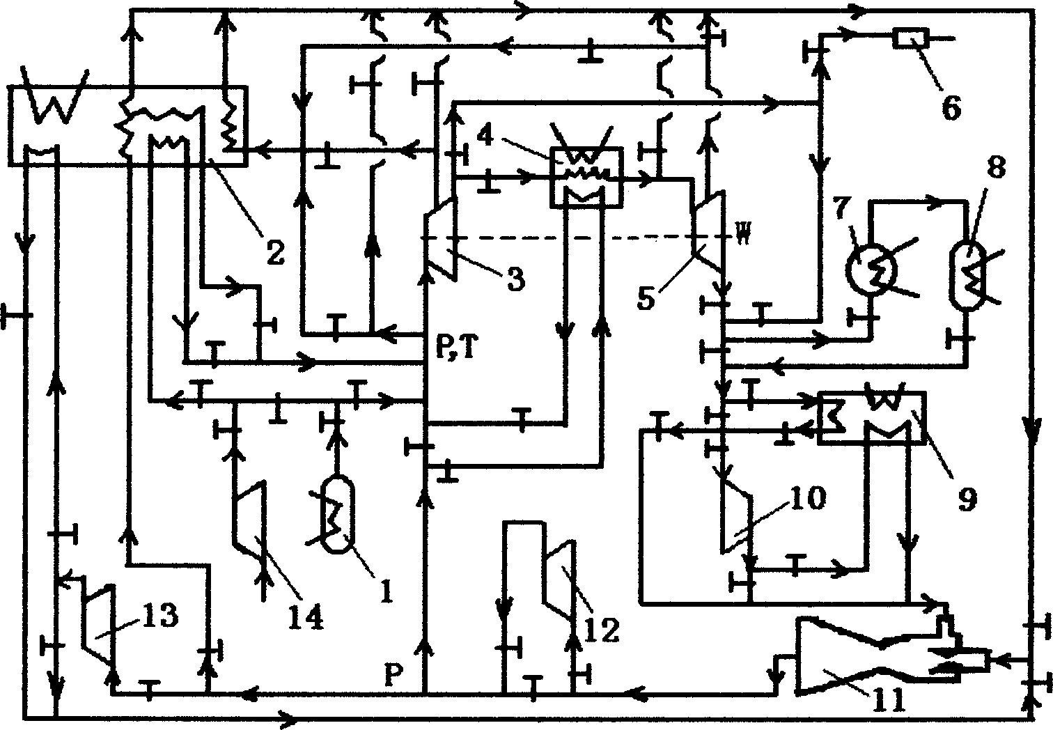
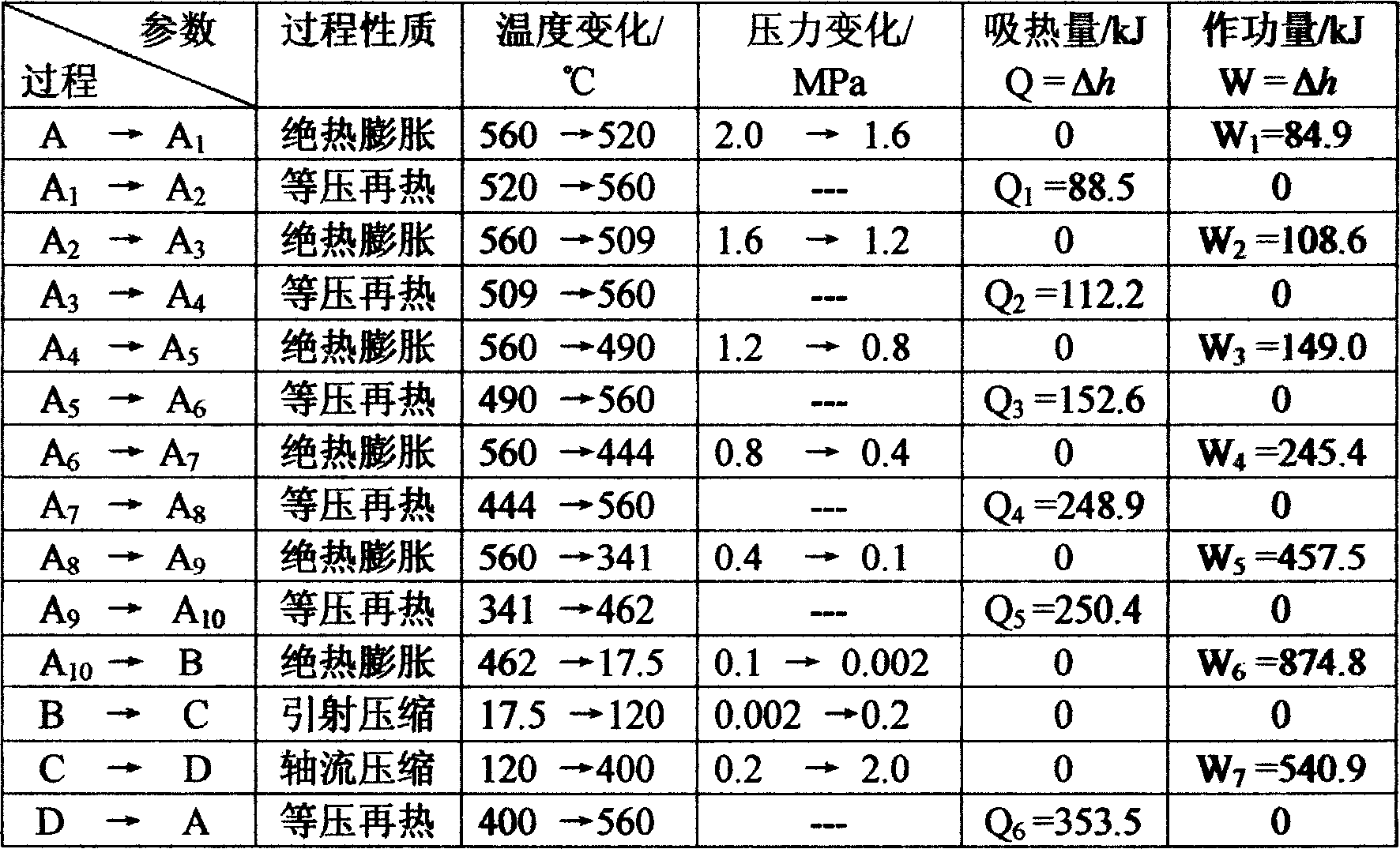
[0022] Embodiment 1: In this embodiment, water vapor is used as a working medium. The system is evacuated by the vacuum pump (6), and the steam generator (1) generates water vapor with an initial pressure of 2.0MPa, which enters the superheater (2) and is heated to become superheated steam with an initial temperature of 560°C, and then enters the turbine (3, 5) Expansion works, and 5 reheat cycles are carried out in the middle. The parameters of each reheat cycle are shown in the appendix figure 2 and the table below, and make the dryness of the exhaust gas coming out from the turbine (5) reach 100%, the exhaust gas (2kPa, 17.5°C) is reheated steam (0.4MPa, 560°C) for the fourth time in the ejector (11) ℃) under the action of ejection to initially compress into 0.2MPa, 120℃ saturated steam, then compressed to 0.4MPa by the compressor (12), and then heated to 560℃ by the superheater (2) to re-reach the initial steam parameters, Enter the next cycle. The parameters of each pr...

Embodiment 2

[0037] Embodiment 2: On the basis of the cycle of Embodiment 1, the heat pump (9) is introduced to absorb heat from the cold source to generate hot water with a temperature of 80 ° C. The exhaust gas is firstly exchanged with the hot water of the heat pump (9) to be heated to 80°C, and then enter the ejector (11) to compress to 0.2MPa, 120°C saturated steam. All the other processes are the same as in Example 1. Then the heat absorbed by the unit working fluid from the heat pump (9) is

[0038] Q hp =Cp(T 2 -T 1 )

[0039] =1.0×(80-17.5)

[0040] =62.5(kJ / kg)

[0041] That is, the enthalpy of exhaust gas after heating becomes h 4 =2533.5+62.5=2596 (kJ / kg)

[0042] Then the mass ratio in the ejector is m 0 / m 1 =(h 1 -h 4 ) / (h 4 -h 3 )

[0043] get m after substituting 1 =10.9%, m 0 = 89.1%.

[0044] That is, the actual heat absorbed by the heat pump is

[0045] Q 8 = m 0 Q hp

[0046] =0.891×62.5

[0047] =55.7(kJ)

[004...


PUM


Abstract

The invention is a thermal circulation for converting heat energy into useful work, comprising a course: after an expander does work on gaseous working medium in original state, the gaseous working medium becomes lean gas without liquid working medium; the lean gas returns to original pressure by a pressure recovery system composed mainly of an jet, and then returns to original temperature by heat pump and superheater; a thermal device for implementing the thermal circulation, comprises the following devices: steam generator, superheater, expander, reheater, vacuum pump, condenser, evaporator, heat pump, compressor, and jet. And the invention has advantage of high thermal efficiency, able to reach and exceed 100%, theoretically.

Description

technical field [0001] The present invention relates to a thermodynamic cycle and device, in particular, to a thermodynamic cycle and device for converting thermal energy into useful work. Background technique [0002] In order to convert thermal energy into useful work, thermodynamic cycles that have been proposed or applied include Otto cycle, Diesel cycle, Brayton cycle, Joule cycle, Stirling cycle, Erikson cycle, Carnot cycle, etc., and Rankine cycle belonging to steam power cycle, etc., there are also some mixed cycles such as binary steam cycle, gas-steam cycle, etc., and subsidiary cycles of the above cycles such as reheat cycle, regenerative cycle, etc. The adoption of the above-mentioned thermodynamic cycles has brought the development of mankind into the era of mechanical power and electric power. Due to theoretical limitations, these thermodynamic cycles and the thermal devices using these thermodynamic cycles have the disadvantage of low thermal efficiency, whic...

Claims


Application Information

Patent Timeline
Patent Type & Authority Applications(China)
IPC IPC(8): F01K27/00
Inventor 陈培豪
Owner 陈培豪
Why Eureka
Try Eureka