Eureka AIR delivers breakthrough ideas for toughest innovation challenges, trusted by R&D personnel around the world.

Two-stage screw compressor

A screw compressor and compression mechanism technology, applied in the direction of rotary piston machinery, mechanical equipment, machine/engine, etc., can solve the problems of increasing the weight of the casting, not considering the increase of noise, and the complexity of the shape of the casting, etc., to achieve a simple structure , Prevention of internal resonance, noise reduction effect

Inactive Publication Date: 2007-01-10
HITACHI JOHNSON CONTROLS AIR CONDITIONING INC
View PDF1 Cites 3 Cited by
  • Summary
  • Abstract
  • Description
  • Claims
  • Application Information

AI Technical Summary

Problems solved by technology

However, in the case of attaching a sound-absorbing material to the casing in the above-mentioned method, it is necessary to cover the entire casting casing with the sound-absorbing material, which is often difficult for a screw compressor having a complicated casting shape.
In addition, there are problems such as making the shell double-structured or adding ribs, which complicates the shape of the casting and increases the weight of the casting
[0005] In addition, any of the prior arts described above, including a low-pressure stage side casing having a low-pressure stage compression mechanism part, a discharge casing provided on the discharge side of the low-pressure stage side casing, a high-pressure stage side casing having a high-pressure stage compression mechanism part, and connecting In the two-stage screw compressor in which the discharge casing and the high-pressure stage side casing house the middle stage casing of the electric motor, the increase in noise due to internal resonance in the discharge casing is not considered.

Method used


Image

  • Two-stage screw compressor
  • Two-stage screw compressor
  • Two-stage screw compressor

Examples


Embodiment Construction

[0015] Embodiments of the present invention will be described below with reference to the drawings.

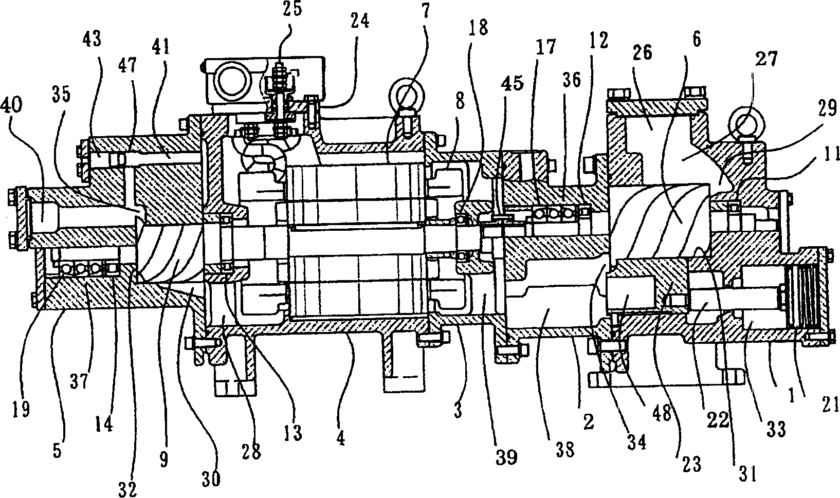
[0016] figure 1 An example of the two-stage screw compressor of the present invention is shown. The screw compressor has: a low-pressure stage casing 1 provided with a suction port 26; a discharge casing 2 connected to the discharge side of the low-pressure stage casing 1 and having a gas passage 38; a motor cover (intermediate stage casing) 3 connected to the discharge side. The downstream side of the casing 2 also has a gas passage 39 and accommodates the coil end 8 of the electric motor 7 ; the motor casing (intermediate stage casing) 4 containing the electric motor 7 ; These components are integrated by bolts or the like.

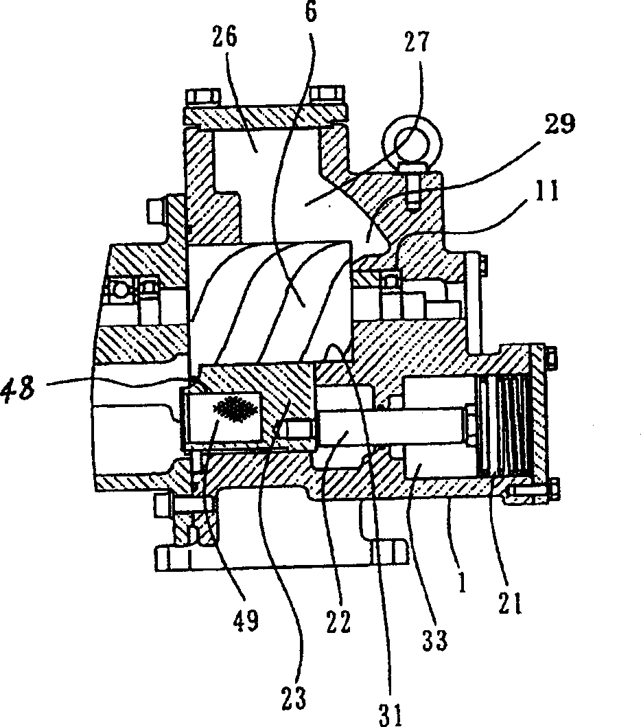
[0017] In the low-pressure stage casing 1, a cylindrical chamber 31, a suction hole 29 for introducing refrigerant gas into the cylindrical chamber 31, a piston chamber 33 for accommodating a piston 21 for driving the spool valve 23, and the like are ...


PUM


Abstract

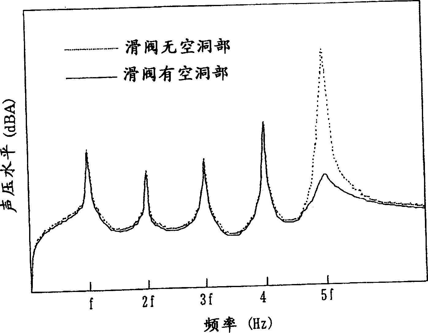
A two-stage screw compressor of the invention includes a low pressure stage casing provided with a low pressure stage compression mechanism, a discharge casing provided on a discharge side of the low pressure stage casing, a high pressure stage casing provided with a high pressure stage compression mechanism, and intermediate stage casings for connecting the discharge casing and the high pressure stage casing, and accommodating an electric motor. In such a two-stage screw compressor, a cavity is formed on a discharge casing side in the slide valve so as to enlarge the capacity of a discharge space formed in the discharge casing. Thereby, internal resonance occurring in the discharge casing is prevented.

Description

technical field [0001] The present invention relates to a two-stage screw compressor for use in screw refrigerators and the like. Background technique [0002] The noise spectrum generated by the screw compressor is known as follows: the product of the number of teeth of the convex rotor and the rotation frequency is the fundamental frequency, and the fundamental frequency and its high harmonic components become obvious peaks. As a method of reducing this noise, there are measures such as attaching a sound-absorbing material to the casing, making the casing double-structured to improve sound insulation performance, or adding ribs to the casing to increase the rigidity of the casing. In a single-stage single-screw compressor, as disclosed in Patent Document 1, in order to reduce noise, a resonance space is provided inside the slide valve, and the resonance space communicates with the compression space to reduce noise. [0003] Patent Document 1: Japanese Patent Laid-Open No....

Claims


Application Information

Patent Timeline
Patent Type & Authority Applications(China)
IPC IPC(8): F04C29/06F04C23/00
CPCF04C29/068F04C29/026F04C23/001F04C28/12F04C18/16
Inventor 加藤英介日置泰宏野泽重和
Owner HITACHI JOHNSON CONTROLS AIR CONDITIONING INC
Why Eureka
Eureka Blog
Learn More