

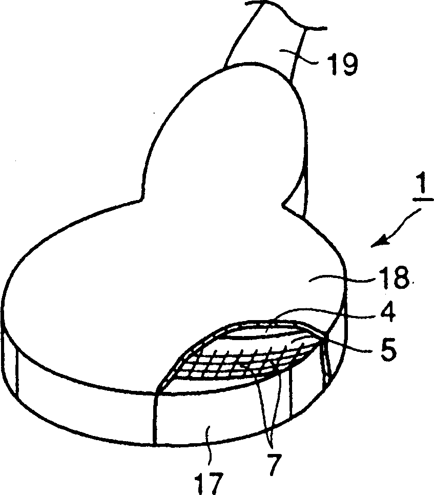
Convex ultrasonic probe and ultrasonic diagnostic apparatus
An ultrasonic and convex technology, applied in ultrasonic/sonic/infrasonic diagnosis, sonic diagnosis, infrasonic diagnosis, etc., can solve problems such as adverse thermal effects, and achieve the effects of preventing multiple reflections, improving image quality, and excellent heat dissipation.
- Summary
- Abstract
- Description
- Claims
- Application Information
AI Technical Summary
Problems solved by technology
Method used
Image

Examples
Embodiment 1
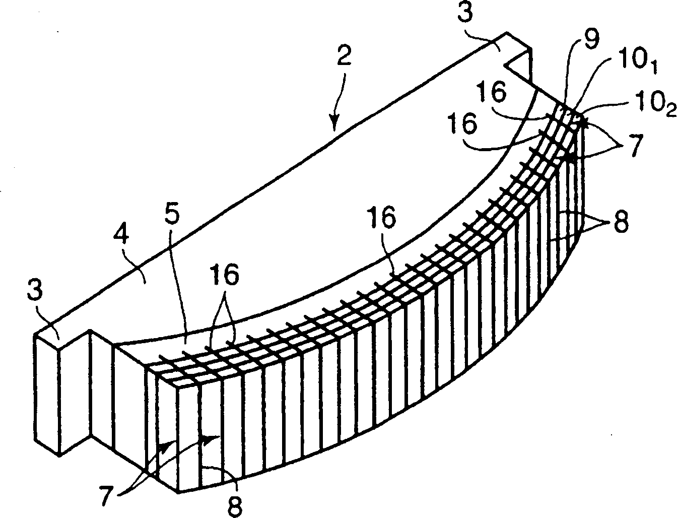
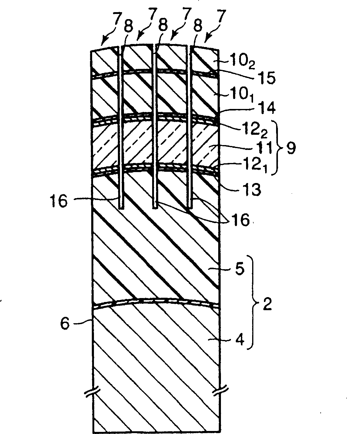
[0086] First, ethylene-vinyl acetate copolymer (EVAC) containing 50% by weight of vinyl acetate was supplied between hot rolls heated to about 70° C., and pre-kneaded for 20 minutes. Then, in 100 parts by weight of EVAC after pre-kneading, add carbon fibers (filler) and dioctylsebacate (dioctylsebacate) with an average diameter of 10 μm and an average length of 20 mm; 6 parts by weight of vulcanizing agent, 2 parts by weight Glycerin Zinc Stearate (vulcanization accelerator), 4 parts by weight of Galvani Wax (Calvani Wax) and 3 parts by weight of silicone resin, and then kneading and flakes for 20 minutes to become a width of 400mm, thickness 0.5mm flakes. In addition, pitch-based carbon fibers having a thermal conductivity of 500 W / m·K were used as the above-mentioned carbon fibers, and the carbon fibers were blended into the kneaded product in an amount of 50% by volume. Next, a circular plate with a diameter of 100 mm was punched out from the sheet. After laminating 40 di...
Embodiment 2
[0090] The same backing member as in Example 1 was produced except that the thickness of the sound absorbing layer was 5 mm. In addition, the outer dimensions of the backing member were the same as in Example 1, and the thickness of the support was reduced by increasing the thickness of the sound absorbing layer to about 5 mm. In addition, a dummy test body of an ultrasonic probe similar to that of Example 1 was assembled using this backing member.
[0091] Reference example 1
[0092] A backing member was produced in the same manner as in Example 1 except that the thickness of the sound absorbing layer was 2 mm. In addition, the external dimensions of the backing member were the same as in Example 1, and the thickness of the support was increased by reducing the thickness of the sound absorbing layer to about 2 mm. In addition, a dummy test body of an ultrasonic probe similar to that of Example 1 was assembled using this backing member.
example 2
[0094] A backing member was produced in the same manner as in Example 1 except that the thickness of the sound absorbing layer was 9 mm. In addition, the outer dimensions of the backing member were the same as in Example 1, and the thickness of the support was reduced by increasing the thickness of the sound absorbing layer to about 9 mm. In addition, a dummy test body of an ultrasonic probe similar to that of Example 1 was assembled using this backing member.
PUM
| Property | Measurement | Unit |
|---|---|---|
| thermal conductivity | aaaaa | aaaaa |
| thickness | aaaaa | aaaaa |
| thermal conductivity | aaaaa | aaaaa |
Abstract
Description
Claims
Application Information