Motor rotor

A technology of motor rotor and rotor body, applied in the direction of magnetic circuit rotating parts, magnetic circuit shape/style/structure, etc., can solve the problems of increased cost, smaller surface area, reduced magnetic flux density of motor rotor 2, etc., to increase torque Effect

Inactive Publication Date: 2007-01-10
DELTA ELECTRONICS INC
View PDF0 Cites 1 Cited by
  • Summary
  • Abstract
  • Description
  • Claims
  • Application Information

AI Technical Summary

Problems solved by technology

For example, if figure 2 The motor rotor 2 in the system is 6 poles, when it is desired to increase the number of poles of the motor rotor 2 to 8 poles (such as image 3 As shown), it is limited by the surface area of ​​the rotor body 21, so that the surface area occupied by each permanent magnet 23 becomes relatively smaller, thus reducing the overall magnetic flux density of the motor rotor 2
In addition, if the air gap is to be reduced, the machining accuracy of the motor rotor surface will be improved, resulting in an increase in cost

Method used


Image

  • Motor rotor
  • Motor rotor
  • Motor rotor

Examples


Embodiment Construction

[0028] A motor rotor according to a preferred embodiment of the present invention will be described below with reference to related drawings.

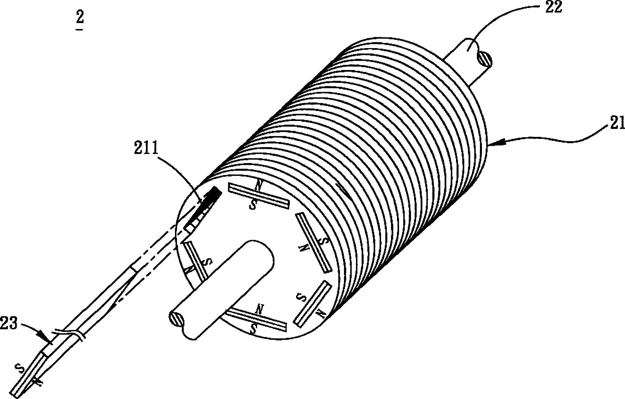
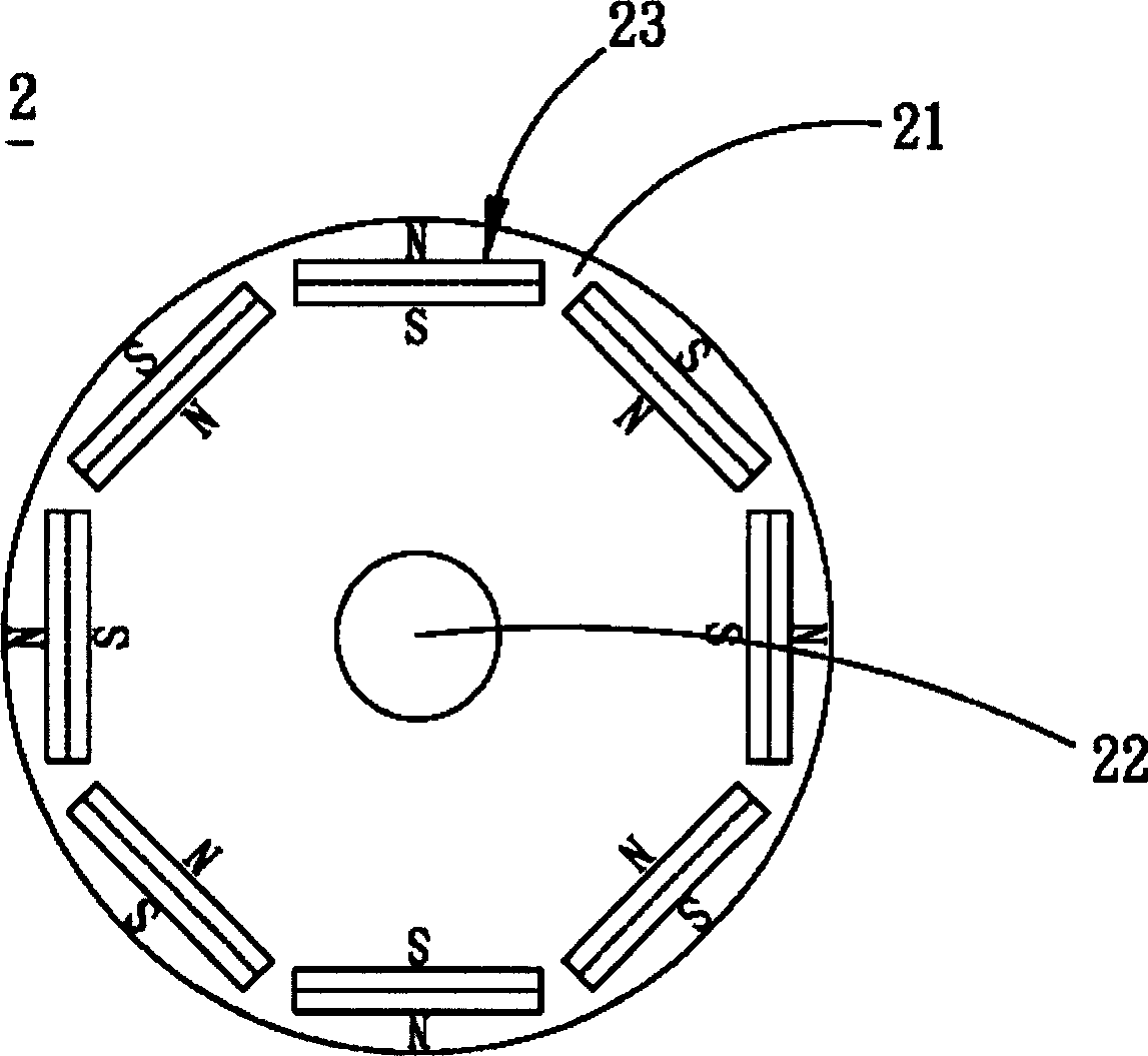
[0029] see Figure 4 as well as Figure 5 As shown in FIG. 1 , are respectively a three-dimensional schematic view and a front view of a motor rotor in a preferred embodiment of the present invention. The motor rotor 3 of this embodiment is a motor inner rotor, which includes a rotor body 31 , a rotating shaft 32 and a plurality of magnetic elements 33 .

[0030] The rotor body 31 of this embodiment has a through hole 311 and a plurality of accommodating portions 312 . The through hole 311 is arranged at the axis of the rotor body 31, and the accommodating portions 312 are arranged radially toward the outer circumference of the rotor body 31 from the rotation axis 32, and these accommodating portions 312 are radially centered on the axis. The rotor body 31 is arranged at equal intervals for accommodating the magnetic elements 33 . ...


PUM


Abstract

The rotor of motor includes a body of rotor, a rotating shaft, and multiple magnetic elements. The body of rotor possesses multiple accommodation parts, which are arranged in radiation form by using axle center of body of rotor as center. The rotating shaft is setup at axle center of body of rotor. Multiple magnetic elements are setup in the accommodation parts. Each magnetic element possesses an N pole and an S pole. Joint seam between N pole and S pole, and extension direction of seam passes through the axle center of body of rotor.

Description

technical field [0001] The present invention relates to a motor rotor, in particular to a magnet-embedded type motor rotor. Background technique [0002] Generally speaking, a permanent magnet motor mainly includes a motor rotor with permanent magnets and a stator with coils. The motor rotor can be rotated after the coil of the stator is energized. At present, the motor rotor is roughly divided into two types, one is the permanent magnet arranged on the surface of the motor rotor, called the surface magnet type, and the other is the motor rotor with a magnet inside. Slots are used to arrange permanent magnets inside the motor rotor and are called embedded magnet types. [0003] see figure 1 , figure 1 Shown is a three-dimensional schematic diagram of a conventional motor rotor. A known surface magnet type motor rotor 1 mainly includes a rotor body 11 , a rotating shaft 12 , and a plurality of permanent magnets 13 . Wherein, the rotor body 11 is composed of a plurality o...

Claims


Application Information

Patent Timeline
Patent Type & Authority Applications(China)
IPC IPC(8): H02K1/27
Inventor 沈德洋游原盈叶鸣
Owner DELTA ELECTRONICS INC
Why Eureka
Try Eureka