Brake disc especially for rail vehicles

A technology for rail vehicles and brake discs, applied in the directions of brake discs, brake types, brake components, etc., can solve the problem of high manufacturing costs of radial grooves and sliders, and achieve simple manufacturing, improved centering quality, and high redundancy. The effect of redundancy

Inactive Publication Date: 2007-01-10
KNORR BREMSE SYST FUR SCHIENENFAHRZEUGE GMBH
View PDF5 Cites 3 Cited by
  • Summary
  • Abstract
  • Description
  • Claims
  • Application Information

AI Technical Summary

Problems solved by technology

[0013] As already mentioned, radial grooves and slides are expensive to manufacture, especially with the necessary machining

Method used


Image

  • Brake disc especially for rail vehicles
  • Brake disc especially for rail vehicles
  • Brake disc especially for rail vehicles

Examples


Embodiment Construction

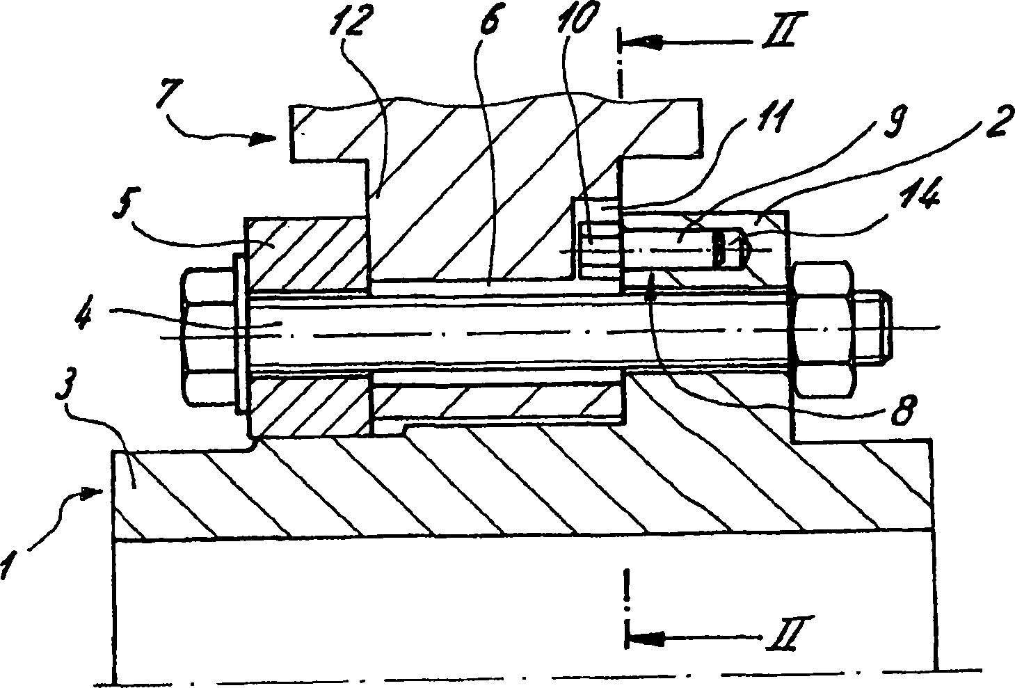
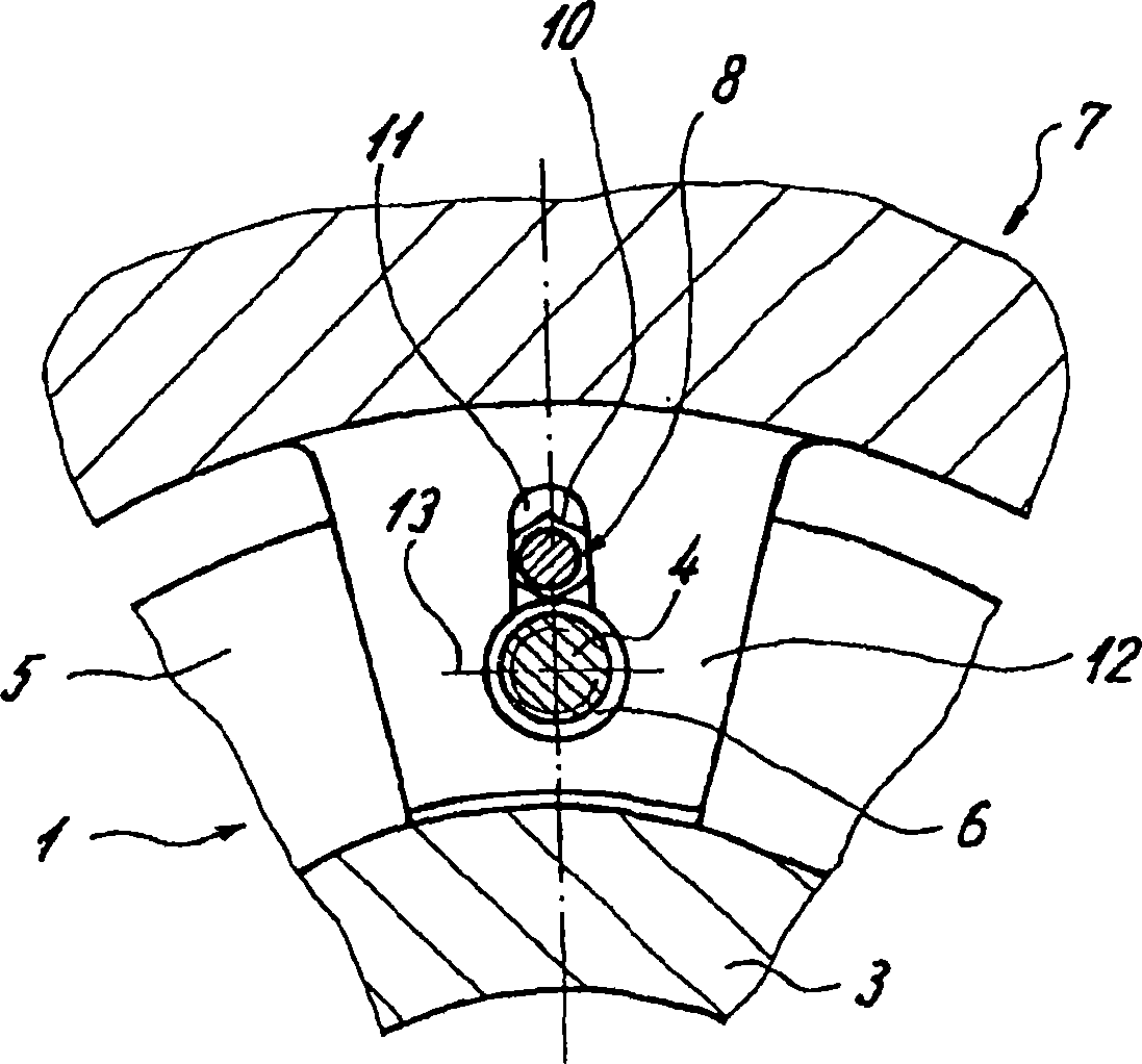
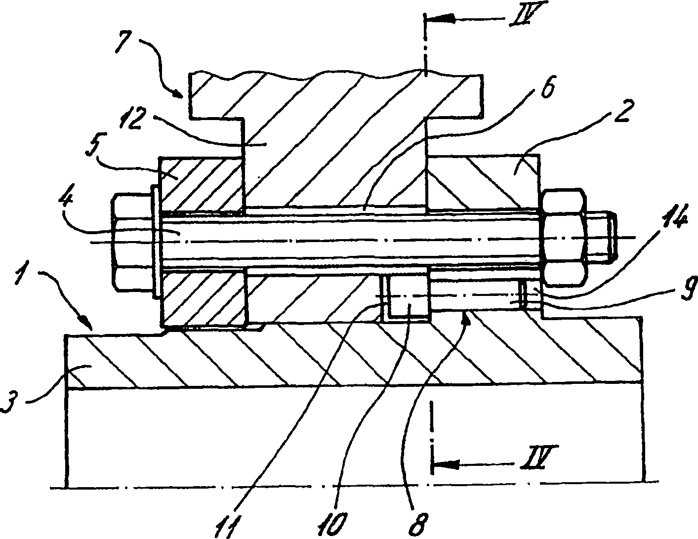
[0036] Figures 1 to 6 Represents the brake disc of the axle brake disc. They are composed of a hub 1 and a friction ring 7 according to their basic structure. The hub 1 includes a hub body 3 extending axially and a surrounding hub body extending radially relative to the hub body. The hub flange 2, the friction ring 7 is fixed on the hub 1 by means of clamping screws 4.

[0037] For this purpose, the clamping screws 4 pass through a clamping ring 5 arranged opposite the hub flange 2 , through the connecting flange 12 assigned to each clamping screw 4 through the friction ring 7 and through the hub flange 2 , wherein the connecting flange 12 has a through hole 6 for passing through the clamping screw 4 and is clamped between the clamping ring 5 and the hub flange 2 .

[0038] In the region of each through hole 6, a radial groove 11 is provided in the connecting flange 12, in the figure 1 In the exemplary embodiment shown, the radial grooves extend from the through-hole 6 to t...


PUM


Abstract

A brake disk, especially for a rail vehicle, comprising at least one friction ring (7) which is provided with radial grooves (11) and which is fixed by means of clamping screws (4) to a hub (1), which can be fixed on a shaft, or a wheel disk. In order to rotationally block and center the friction ring (7), sliding elements (8) which are connected to the hub (1) or wheel disk are engaged in the radial grooves (11). Each sliding element (8) is embodied as a guide pin whose shaft (9) extends in an axis-parallel manner in relation to the clamping screw (4) and which is produced from a semi-finished product or standard part.

Description

technical field [0001] The invention relates to a brake disk, in particular for rail vehicles, according to the preamble of claim 1 . Background technique [0002] Such brake discs, which are used as so-called axle or wheel brake discs, are subjected to high mechanical and thermal loads during operation, and they require special structural measures in order to guarantee the necessary reliability on the one hand and on the other hand Assembly or disassembly can be performed midway for replacement. [0003] Since the friction ring expands due to the heating caused by braking, simple centering on the hub of the axle brake disc, for example via a cylindrical seat, is not sufficient, especially in the case of two-part high-performance brake discs of. It is therefore known to fasten a slider in the form of a slider on the hub. They are guided in radial grooves of the respective friction ring, so that despite radial expansion of the friction ring, the centering is maintained by ...

Claims


Application Information

Patent Timeline
Patent Type & Authority Applications(China)
IPC IPC(8): F16D65/12
CPCF16D65/123F16D2065/1384F16D2065/138F16D2065/136F16D2065/1392
Inventor 克萨韦尔·维尔特克里斯蒂安·莫斯巴赫
Owner KNORR BREMSE SYST FUR SCHIENENFAHRZEUGE GMBH
Why Eureka
Try Eureka