
Shock-proof bundled energy clearing slope support

A technology of anti-seismic beams and diagonal braces, applied in the direction of anti-seismic, building components, etc., can solve problems such as reduced operating efficiency, inability to plug and install, and difficulty in controlling precision

Inactive Publication Date: 2007-01-24
任德威 +4
View PDF0 Cites 4 Cited by
  • Summary
  • Abstract
  • Description
  • Claims
  • Application Information

AI Technical Summary

Problems solved by technology

[0006] However, this butt joint method not only increases a large number of joint welding operations, but also makes the joint part quite complicated and crowded; in addition, under the premise that the joint transmits an equal amount of axial force, the bolts required for the butt joint are used Quantity will be double that with lap joints
As a result, when installing this kind of brace, it may be very labor-intensive and time-consuming, the work efficiency will be reduced, and the quality will not be easy to control
[0007] see Figure 2~4 As shown, some people have researched and proposed a plug-in energy-dissipating diagonal brace. Although this plug-in energy-dissipating diagonal brace reduces the use of bolts and the use of butt steel plates, this plug-in energy-dissipating diagonal brace The cross-section configuration of the brace is to insert two strip-shaped steel plates 21 of equal cross-section with a fixed parallel distance into a bundle unit 22 composed of a steel pipe and concrete. The distance between the strip-shaped steel plates 21 is not easy to locate, nor is it easy to control its precision, and the installation of the plug-in joint surface 23 and the joint corner plate 24 is directional. If the distance between the two strip-shaped steel plates 21 is positioned Poor, and if the length of the diagonal brace is often greater than the beam span or column height when it is installed in a single oblique direction, the installation efficiency will definitely be reduced, and it will even be impossible to insert and install

Method used


Image

  • Shock-proof bundled energy clearing slope support
  • Shock-proof bundled energy clearing slope support
  • Shock-proof bundled energy clearing slope support

Examples


Embodiment Construction

[0063] The invention is illustrated by two combinations, where Figure 5-17 It is an energy-dissipating diagonal bracing made of bundled joints; and Figures 18-38 The energy-dissipating diagonal bracing for the improved splicing bundle is now described in detail in conjunction with the illustrations and examples:

[0064] see Figure 5-9 As shown, the first embodiment of a lap joint combined energy-dissipating brace 3 of the present invention includes a main stress unit 31 and a restraint unit 32, and the main stress unit 31 and the restraint unit 32 are respectively It is a pair of glyph-shaped main force-bearing members 311 and a pair of double-steel steel enclosure members 3211 that are independently formed. The end section of the main force-receiving member 311 is larger than that of the middle section, and is inserted through the enclosure of the binding unit 32 Component 3211, the bolt holes 33 on the overlapping joint surfaces at both ends of the main force-bearing c...


PUM


Abstract

The inclined piece is composed of main stress unit and tying and binding unit mainly. The main stress unit is composition of steel members possessing mono symmetrical or bisymmetric sections in any shapes in open or close types. Sections at end parts larger than section at middle part are sheathed to the tying and binding unit. Being assembled from components of single or multiple steel tubes with concrete, sand-cement slurry or stiffened members being filled or installed inside tubes, the tying and binding unit as a body of outline border is in use for tying and binding the main stress unit. Being matched to end part of the inclined piece in modes of lap joint or socket joint, the tying and binding unit is connected to structure. The inclined piece is steady no mater stress or pull are applied. The disclosed inclined piece increases capability of anti plastic deformation so as to reach effect of reducing vibration and earthquake force.

Description

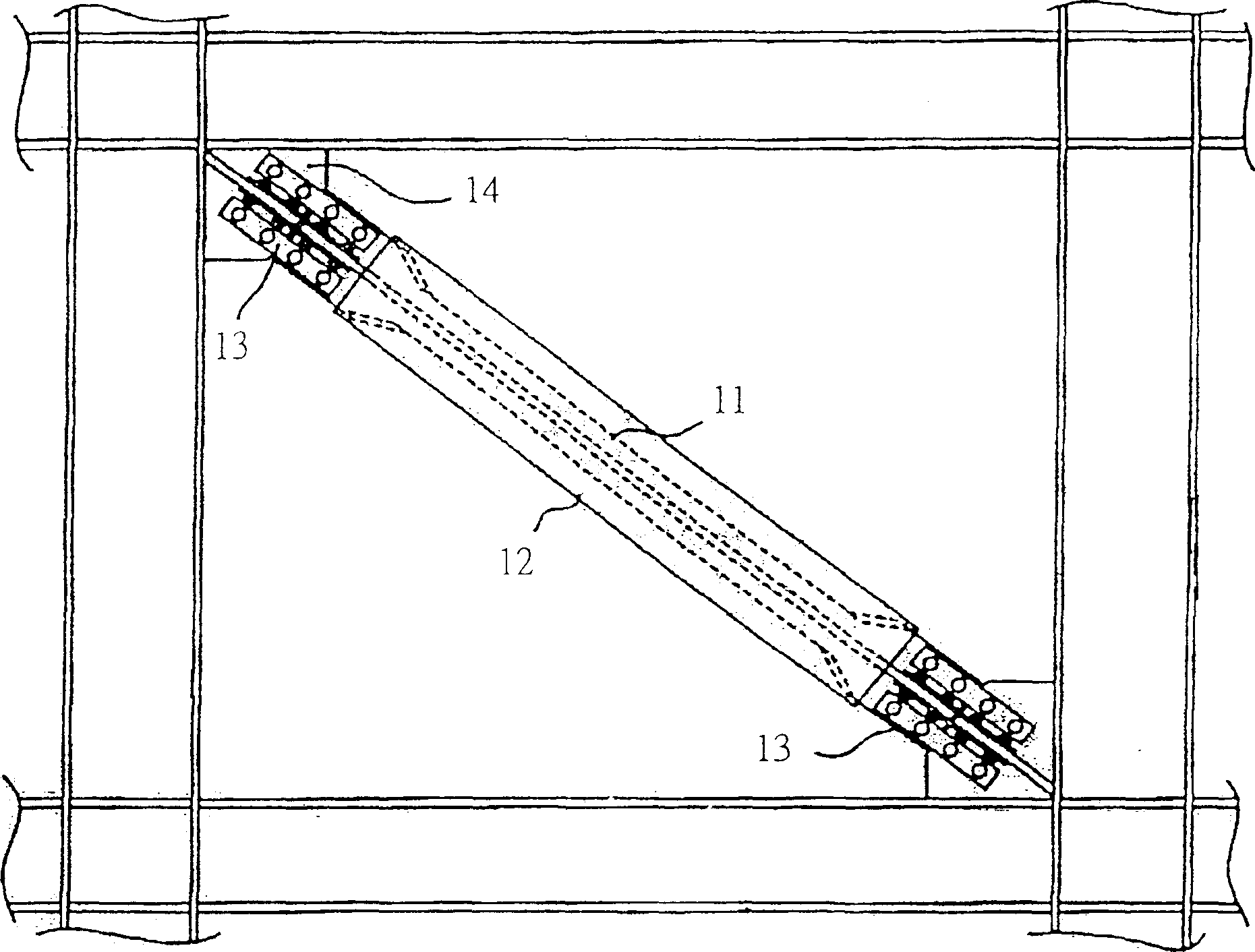
technical field [0001] The invention relates to a building material component, in particular to an anti-seismic bundle energy-dissipating diagonal brace which can improve the plastic deformation capacity of the diagonal brace, reduce vibration and earthquake force. Background technique [0002] When the traditional diagonal bracing member is subjected to axial pressure, it will produce overall deformation and local deformation, and its hysteretic curve shows the behavior of gradually decreasing strength and shrinkage. Concentrated and broken. Over the years, earthquake engineering researchers have started to improve the performance of traditional diagonal braces, and some units have successively published bundled braces that can prevent deformation to replace and improve the function of traditional diagonal braces. [0003] see figure 1 As shown, the braced brace is composed of the main stress unit 11 and the brace unit 12, the axial force (tension and compression) of the ...

Claims


Application Information

Patent Timeline
Patent Type & Authority Applications(China)
IPC IPC(8): E04B1/98
Inventor 任谅恭王亚勇任德威
Owner 任德威
Learn More