Underground infiltration irrigation device, its compensation core, and utilization method for said device
An underground infiltration irrigation and compensation technology, applied in the direction of botany equipment and methods, applications, root water feeders, etc., can solve the problems of difficult and easy construction process, high cost and low cost, etc., to achieve less evaporation loss and simple structure , good irrigation effect
- Summary
- Abstract
- Description
- Claims
- Application Information
AI Technical Summary
Problems solved by technology
Method used
Image
Examples
Embodiment 1
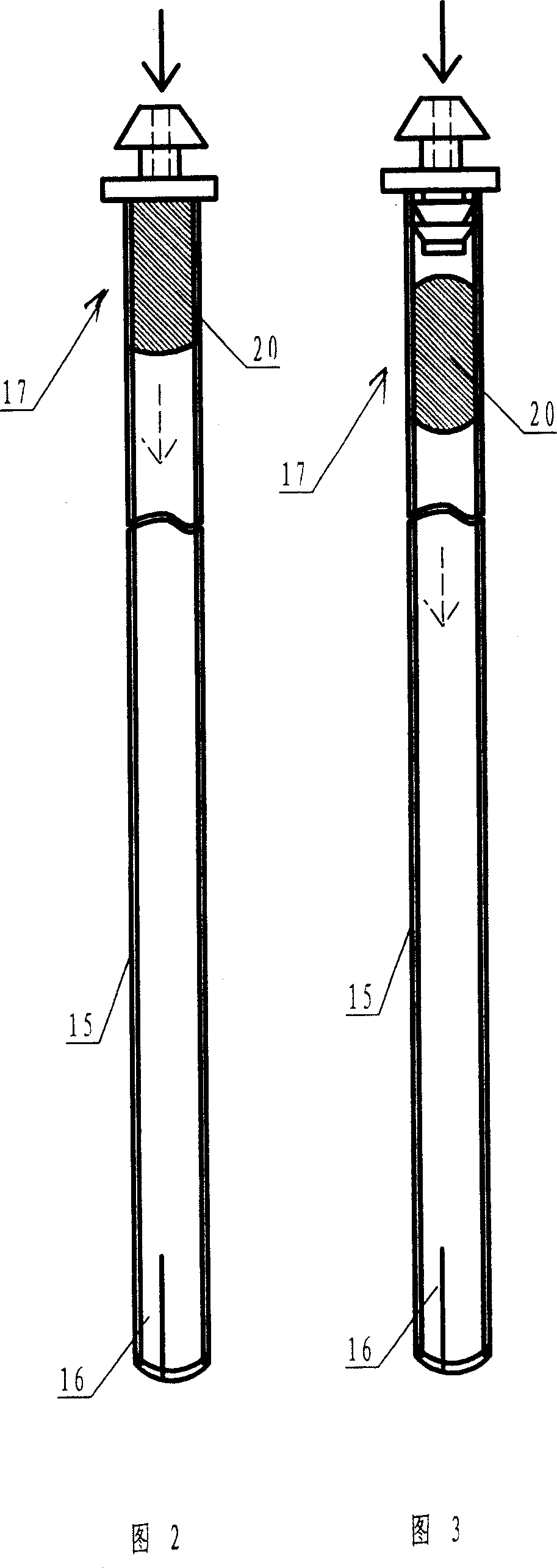
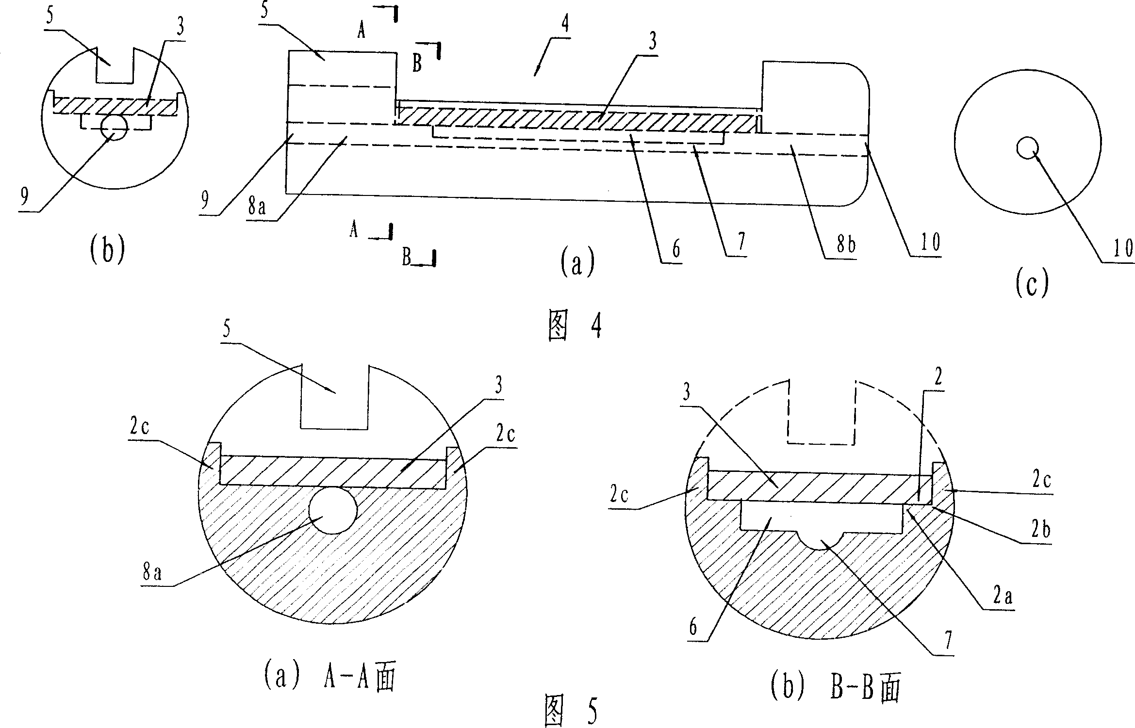
[0057] Embodiment 1: Put elastic piece 3 on Image 6 The shown elastic sheet is placed on the platform 2 to form an elastic sheet compensation type core body 1; the elastic sheet compensation type core body 1 is inserted into the infiltration catheter 15 (see Figure 7 ), and then insert the water outlet of the common bypass at the same end (see Figure 3). Go out a length and be 5 to 10 centimetres, form the subterranean percolator of a kind of structure, stand-by; The bypass piece on this subterranean percolator to be used is inserted in the incoming water pipe (the incoming water pipe can be laid on the ground surface, It can be buried in the ground, and the water pipe can also be hung in the air in a greenhouse environment), and underground irrigation can be implemented. When the pressurized liquid, such as irrigation water or liquid fertilizer, enters the underground irrigation device from the water pipe, after being decompressed by an independent or non-independent decom...
Embodiment 2
[0059] Embodiment 2: The elastic sheet 3 is placed on the elastic sheet placement table 2 as shown in Figure 8 to form an elastic sheet compensation type core 1 with a bypass structure; on the elastic sheet compensation type core 1, the sleeve Go up the percolation irrigation conduit 15 of sufficient length (the length of conduit is determined according to the size of tree strain), after leaving a section of empty pipe, open otch at the afterbody of percolation irrigation conduit, form the underground percolator of a kind of structure, stand-by; The standby underground irrigation device is inserted into the water supply pipe, and one end of the irrigation conduit with a cut is sent into the root region of the tree to implement underground irrigation.
Embodiment 3
[0060] Embodiment 3: when tree strain is bigger, need to arrange underground irrigation device around tree strain, at this moment, can adopt such as Figure 11 In the shown elastic sheet compensating core body with a three-way diverter head, a permeation tube conduit of sufficient length is put on the core body, and after leaving a section of empty tube, an incision is made at the tail of the permeation irrigation conduit to form a The elastic sheet compensation type underground irrigation device of the three-way diverter head, referred to as the three-way underground irrigation device, is for use. Cut the water pipe (usually capillary) for the tree into several sections (the number of sections is determined according to the number of underground irrigation devices required by the tree. For example, if you want 3 underground irrigation devices, you need to cut twice , into three sections), install a spare three-way underground infiltrator at the first cut (see Figure 12), and ...
PUM
 Abstract
Description
Claims
Application Information
 - R&D
- Intellectual Property
- Life Sciences
- Materials
- Tech Scout
- Unparalleled Data Quality
- Higher Quality Content
- 60% Fewer Hallucinations
Browse by: Latest US Patents, China's latest patents, Technical Efficacy Thesaurus, Application Domain, Technology Topic, Popular Technical Reports.
© 2025 PatSnap. All rights reserved.Legal|Privacy policy|Modern Slavery Act Transparency Statement|Sitemap|About US| Contact US: help@patsnap.com


