

Medical use carrier for transferring patient
A technology for transferring a car and a patient, which is applied in the field of medical patient transfer car to achieve the effect of reducing resistance and friction, easy to use and small resistance
- Summary
- Abstract
- Description
- Claims
- Application Information
AI Technical Summary
Problems solved by technology
Method used
Image

Examples
Embodiment Construction
[0060] The present invention will be described in further detail below in conjunction with accompanying drawing embodiment:
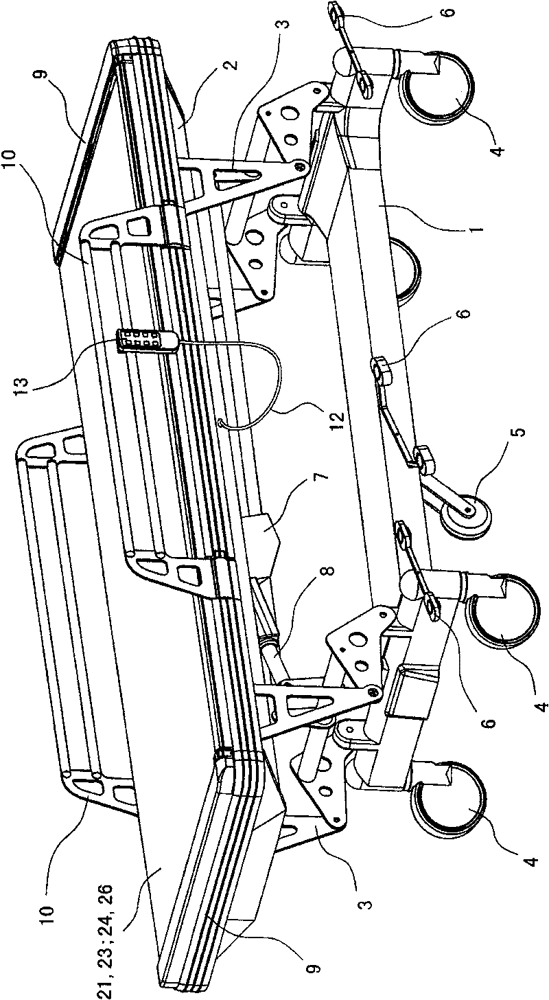
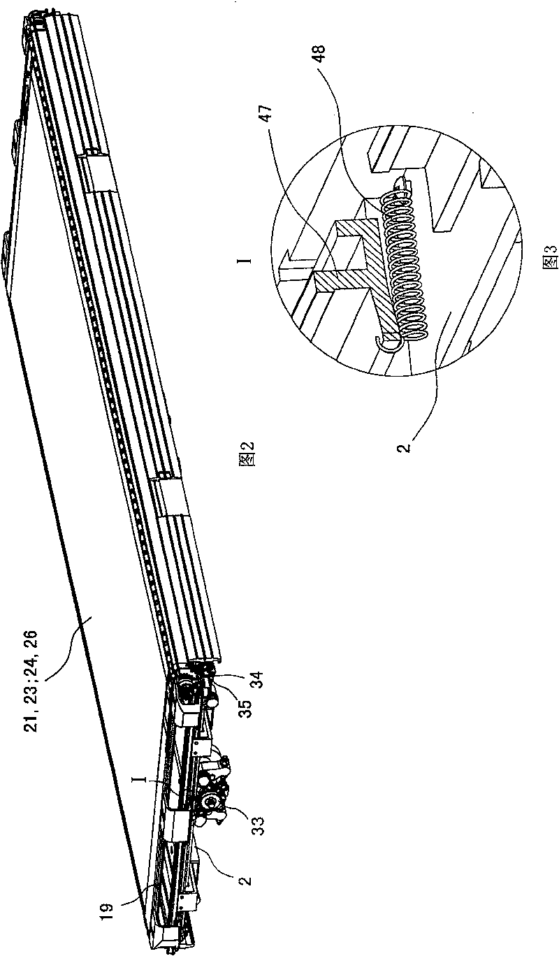
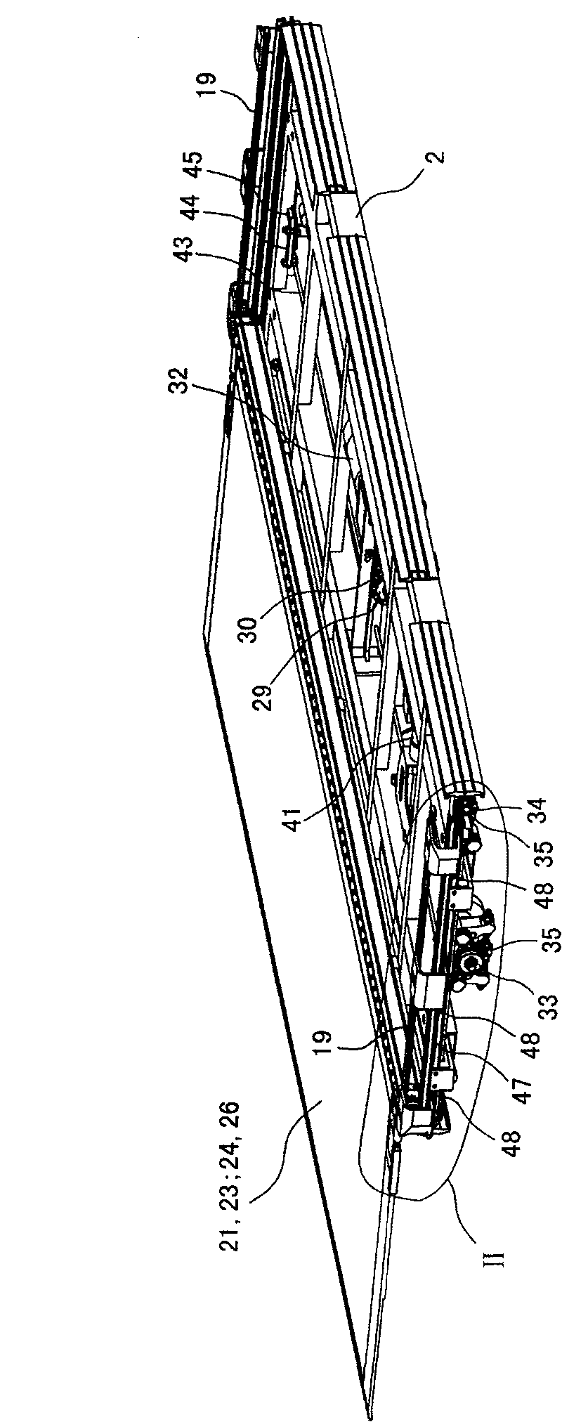
[0061] Such as Figure 1 to Figure 25 It is a preferred embodiment of the present invention. Such as Figure 1 to Figure 25 As shown, the medical patient transfer vehicle in this embodiment has a left-right symmetrical structure, and it has a vehicle body and a moving plate mechanism that can move laterally under the drive of the driving mechanism.
[0062] Car body is made of base 1, vehicle frame 2 (referring to Figure 4 ~ Figure 7 ) and the elevating support 3 connected between the base 1 and the vehicle frame 2 etc. constitute. The bottom of base 1 is equipped with universal caster 4 and guide caster 5, and the universal caster 4 of guide caster 5 and the car body rear side is also provided with brake pedal 6, so that the operator brakes transfer vehicle easily. The elevating support 3 is driven by the elevating motor 7 installed on the bottom ...
PUM
 Abstract
Description
Claims
Application Information