

Core shooting machine having automatic cleaning function
An automatic cleaning and core shooting machine technology, applied in the field of core shooting machines, can solve the problems of shortened service life, incomplete cleaning, high labor intensity, etc., and achieve the effect of easy cleaning and replacement
- Summary
- Abstract
- Description
- Claims
- Application Information
AI Technical Summary
Problems solved by technology
Method used
Image

Examples
Embodiment Construction
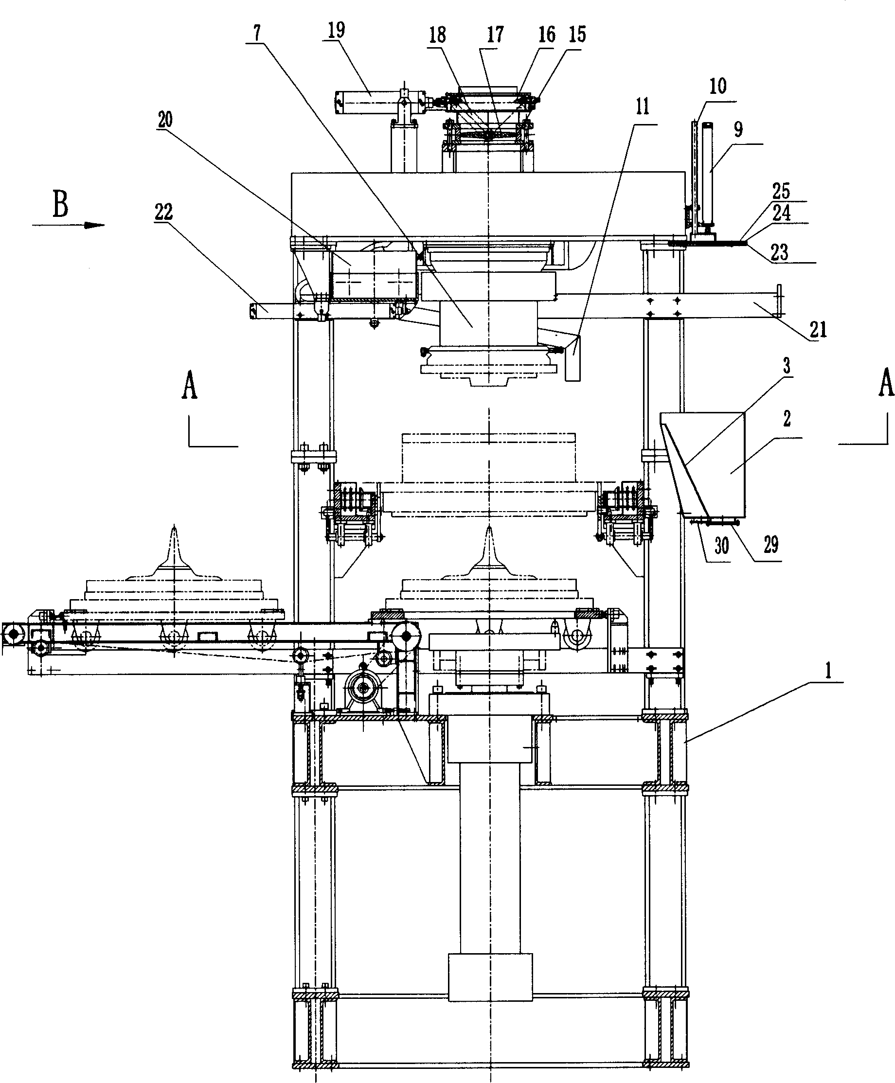
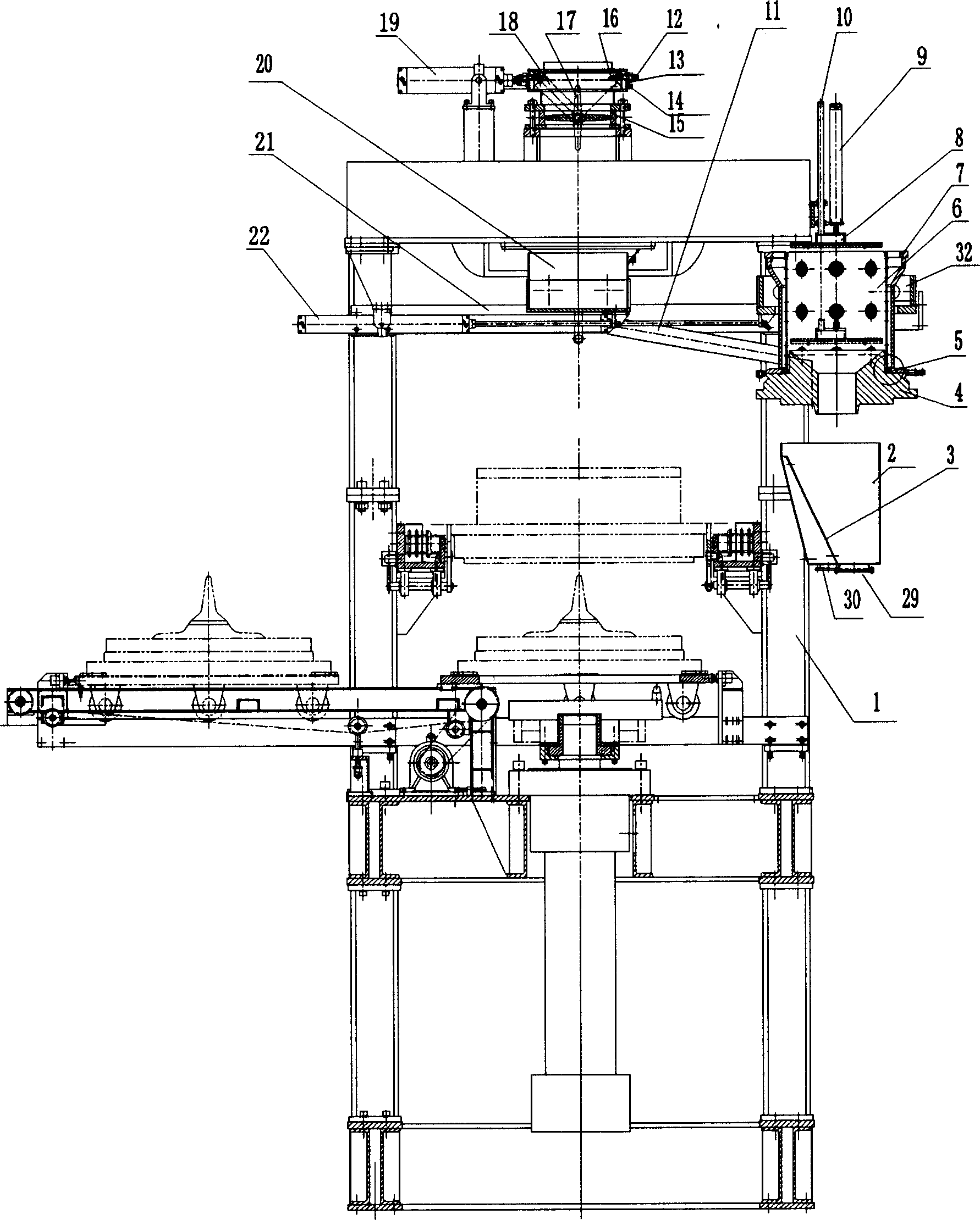
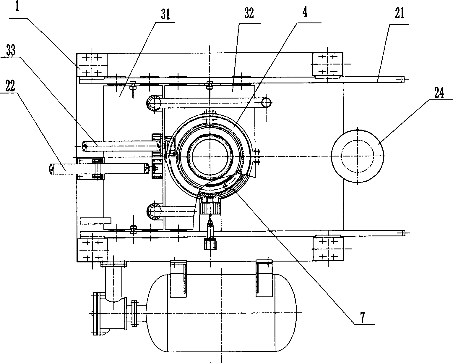
[0024] The core shooter of the present invention will be described in detail below in conjunction with the accompanying drawings.
[0025] as attached Figure 1-8 As shown, the core shooting machine with automatic cleaning function of the present invention is provided with a butterfly valve automatic spray cleaning device on the top of the core shooting machine frame 1, and a lifting type shooting device is provided on the upper right side of the core shooting machine frame 1. The automatic spraying device for the sand cylinder is equipped with a sewage collection bucket 2 below the automatic spraying device for the lifting sand shooting cylinder, and the automatic spraying device for the butterfly valve and the automatic spraying device for the lifting sand shooting cylinder are located on the upper part of the frame 1 of the core shooter. The lower part of the device is horizontally provided with a track 21, and the track 21 is respectively provided with a mobile trolley 32 ...
PUM
 Abstract
Description
Claims
Application Information