
Robot tool centre point three-component calibration method based on plane measurement

A tool center point, flat plate measurement technology, applied in measurement devices, manufacturing tools, instruments, etc., can solve problems such as large changes in robot joints, multi-robot system errors, and reduced calibration accuracy.

Inactive Publication Date: 2007-01-31
天津智通信息系统集成有限公司
View PDF0 Cites 15 Cited by
  • Summary
  • Abstract
  • Description
  • Claims
  • Application Information

AI Technical Summary

Problems solved by technology

In terms of operation, this method requires the operator to control the robot to a fixed space point with several attitudes with large differences, so as to reduce the correlation of the variables to be solved, but this method is difficult to quantify in operation
And because the joints of the robot change greatly during the calibration process, more robot system errors are introduced during the calibration process, which will affect the calibration accuracy
In addition, this method usually uses the human eye to judge whether the center point of the tool coincides with the fixed point in space, which inevitably introduces human eye judgment errors during the calibration process and reduces the calibration accuracy.

Method used


Image

  • Robot tool centre point three-component calibration method based on plane measurement
  • Robot tool centre point three-component calibration method based on plane measurement
  • Robot tool centre point three-component calibration method based on plane measurement

Examples


Embodiment 1

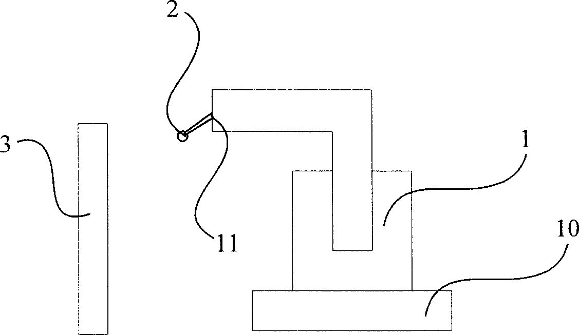
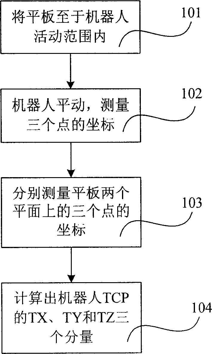
[0024] Embodiment 1: as figure 1 As shown, it is a structural schematic diagram of Embodiment 1 of the present invention, the robot 1 is a six-degree-of-freedom industrial robot, the base 10 is the robot base, tool0 is the coordinate system of the robot end 11, and the measuring probe 2 is fixed on the robot end. Also included is a flat plate 3 with a known thickness. Such as figure 2 Shown, be the flowchart of robot TCP three-component calibration method of the present invention, comprise the following steps:

[0025] Step 101: placing a plate with a flat surface within the range of activity of the robot;

[0026] Step 102: The robot maintains a certain movement direction and moves in translation, measures the coordinates of three or more points on the surface that are not on a straight line, and uses these coordinates to calculate the normal vector of the plane where the surface is located;

[0027] It can be proved that in the measurement of the plane normal vector, onc...

Embodiment 2

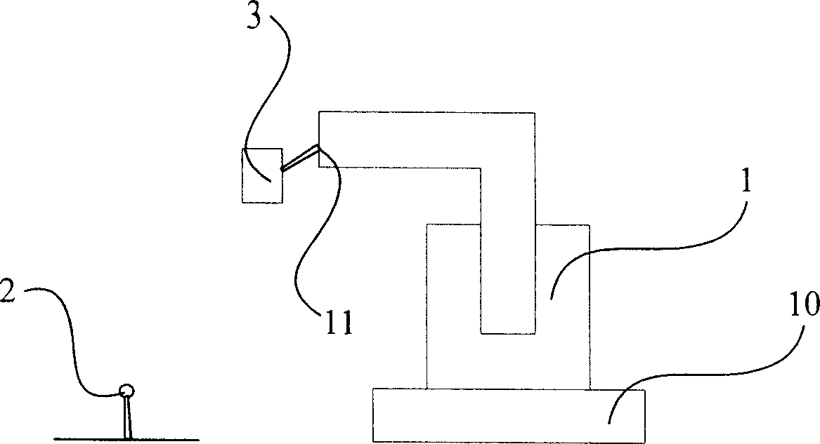
[0107] Such as image 3 As shown, it is a structural schematic diagram of Embodiment 2 of the present invention. The robot 1 is a six-degree-of-freedom industrial robot, the base 10 is the robot base, tool0 is the coordinate system of the robot end 11, and a flat plate 3 with a flat surface is fixed on the robot end. The two surfaces of the flat plate are the first surface and the second surface, and are parallel to each other, and the probe 2 is placed on the ground. Such as Figure 4 As shown, it is a schematic flow chart of the fixed TCP three-component calibration method of the robot of the present invention, including the following steps:

[0108] Step 201: placing the measuring probe within the range of motion of the robot;

[0109] Step 202: The robot maintains a certain movement direction and moves in translation, measures the coordinates of three or more points on the first surface that are not on a straight line, and uses these coordinates to calculate the normal v...


PUM


Abstract

A three-component calibration method based on plate measurement for the central point of robot tool includes such steps as fixing a measuring probe to the terminal of robot, positioning a smooth plate in the moving range of robot, making the robot to move in translation mode, using probe to contact with 3 or more points which are not on a same straight line to obtain their coordinates and positions, calculating the normal components of the plane where the surface is positioned, using probe to contact with one point on the plate when the directions of the X,Y and Z axes for the coordinate system of robot terminal is same as said normal components, measuring the coordinate of the point, and calculating the position of the central point of robot tool in the coordinate system of robot terminal.

Description

technical field [0001] The invention relates to a three-component calibration method for a robot tool center point, in particular to a three-component calibration method for a robot tool center point that is independently calibrated based on the three-component robot tool center point on a geometric plane by measuring the coordinates of points on a flat plate. Background technique [0002] Robot TCP (Tool Center Point) calibration refers to the calibration of the position of the center point of the tool in the end coordinate system of the robot (for the tool held by the robot) or the robot base coordinate system (for the case where the tool is fixed), usually Next, each parameter of robot TCP can be obtained by two methods. One is to measure all the variables of TCP separately, and then use constraints to calculate all the variables of TCP at the same time. Another method is to measure all the variables of TCP separately, and then calculate them separately, and only calcula...

Claims


Application Information

Patent Timeline
Patent Type & Authority Applications(China)
IPC IPC(8): B25J19/00G01B21/24
Inventor 汤青甘中学吴水华宁随军孙云权
Owner 天津智通信息系统集成有限公司
Learn More