Rear buffer configuring structure of two-wheels motor vehicle

A technology of two-wheeled motor vehicle and configuration structure, which is applied in the direction of axle suspension, bicycle accessories, transportation and packaging, etc., to achieve the effect of avoiding interference

Inactive Publication Date: 2007-01-31
HONDA MOTOR CO LTD
View PDF1 Cites 6 Cited by
  • Summary
  • Abstract
  • Description
  • Claims
  • Application Information

AI Technical Summary

Problems solved by technology

[0005] On the other hand, in recent years, there has been proposed a two-wheeled motor vehicle in which a fuel injection device is used to supply fuel to an engine. The top of the shelf protrudes greatly

Method used


Image

  • Rear buffer configuring structure of two-wheels motor vehicle
  • Rear buffer configuring structure of two-wheels motor vehicle
  • Rear buffer configuring structure of two-wheels motor vehicle

Examples


Embodiment Construction

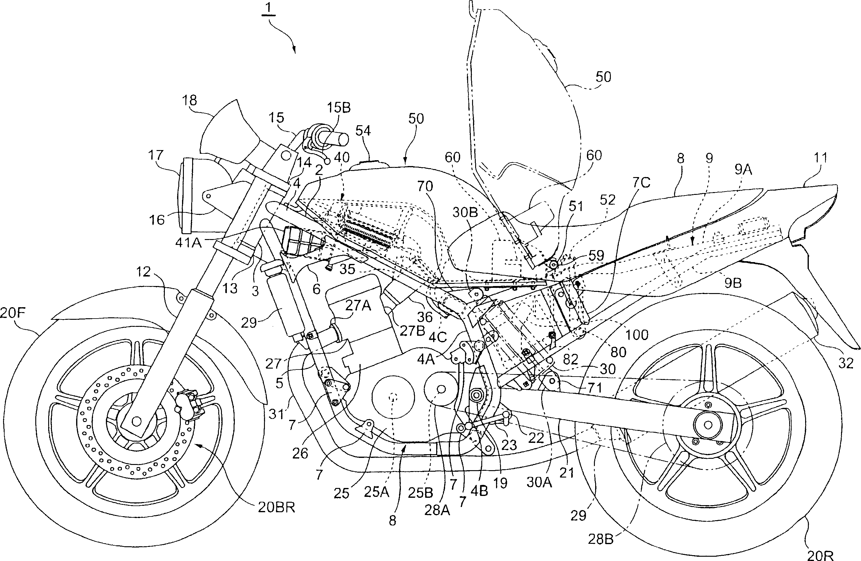
[0040] Hereinafter, an embodiment of the present invention will be described with reference to the drawings. In addition, descriptions of front, rear, left, right, and up and down directions in the description are relative to the vehicle body.

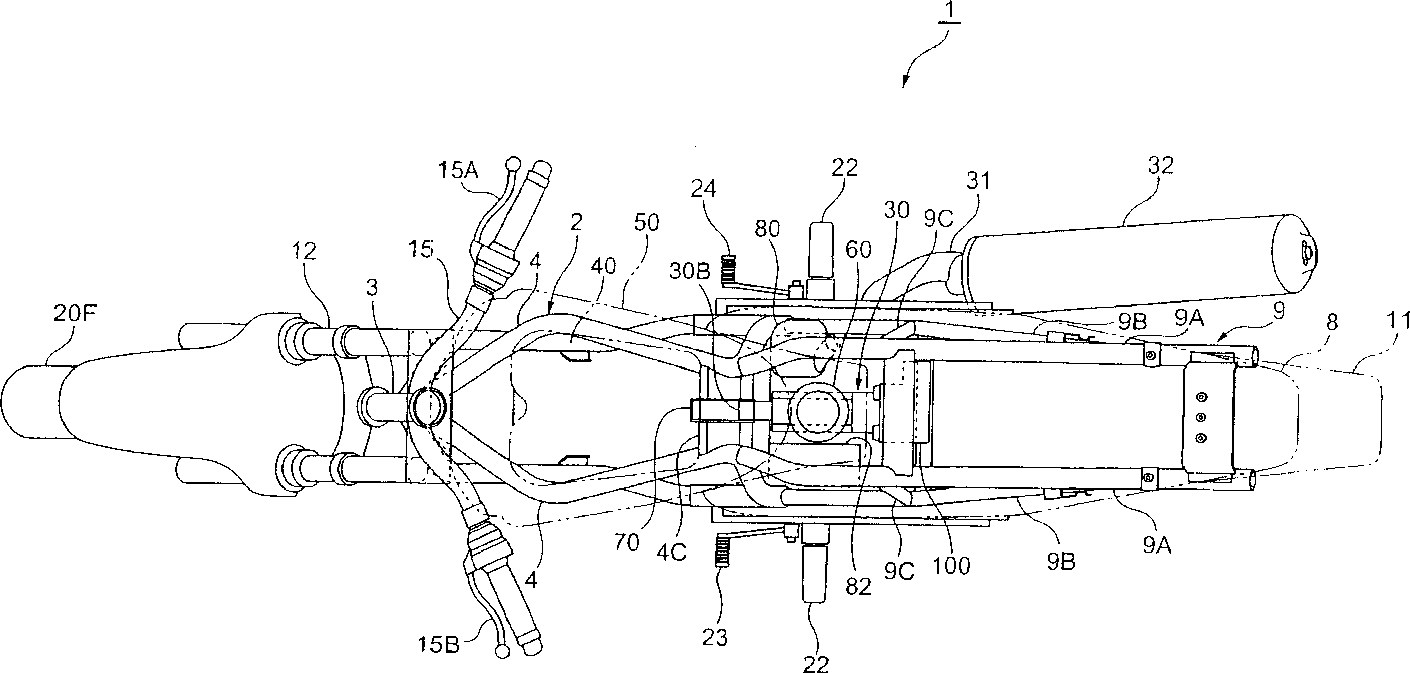
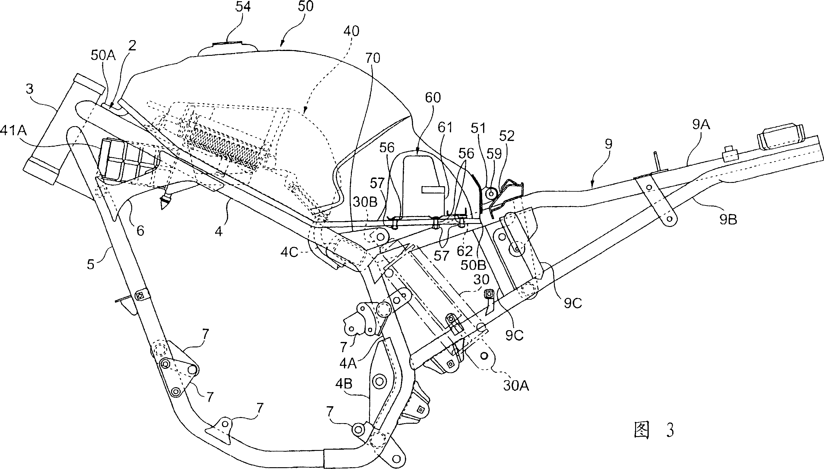
[0041] figure 1 It is a side view showing the overall structure of the motorcycle of this embodiment, figure 2 is the above picture. This motorcycle 1 has a body frame 2 formed by joining a head pipe 3 , a pair of left and right main frames 4 , and a pair of left and right down pipes 5 into a substantially ring shape by welding. The main frame 4 has a downwardly extending portion 4A that extends substantially linearly from the head pipe 3 toward the rear and downward of the vehicle body, and bends from the rear end of the straight portion toward the downward direction of the vehicle body in an approximately inverted C shape. The main frame 4 and the down tube 5 are connected to each other by a reinforcement frame 6 in the vicinity ...


PUM


Abstract

The invention provides a rear cushion arranging structure of an auto-bicycle capable of avoiding reduction of capacity of a fuel tank while sufficiently securing a rear cushion stroke even in directly supporting a lower part of the rear cushion on a rear fork. This auto-bicycle 1 is furnished with a body frame 2 having a main frame 4 and a seat rail 9 extending to the rear of the body from this main frame 4 and the rear cushion 30 arranged between this body frame 2 and the rear fork axially supporting a rear wheel, the fuel tank 50 is arranged in such a way as to straddle over the main frame 4 and the seat rail 9, a fuel pump 60 is arranged on a rear part of a bottom part of this fuel tank 50, and an upper end of the rear cushion 30 is positioned to the front of the fuel pump 60 by projecting it upward from the seat rail 9.

Description

technical field [0001] The present invention relates to a rear buffer arrangement structure of a two-wheeled vehicle capable of ensuring a sufficient rear buffer stroke and avoiding a decrease in the capacity of a fuel tank. Background technique [0002] Conventionally, there is known a two-wheeled motor vehicle employing a single shock absorber structure in which one rear shock absorber absorbs the impact transmitted from the rear wheel to the vehicle frame via the rear fork. In this type, in order to ensure a sufficient rear buffer stroke, it is proposed to extend the lower end of the rear buffer below the rear fork, connect the link to the lower end, and support the lower end of the rear buffer on the rear via the link. On the fork, the upper end of the rear buffer is supported on the frame (for example, refer to Patent Document 1) [0003] Patent Document 1: Japanese Patent No. 2673894. [0004] However, some motorcycles also have a structure in which, for example, the...

Claims


Application Information

Patent Timeline
Patent Type & Authority Applications(China)
IPC IPC(8): B62K25/26B62J35/00B62J99/00
Inventor 西山弘忠
Owner HONDA MOTOR CO LTD
Why Eureka
Try Eureka