Air conditioner condensation water divided flow box

A technology for air conditioners and condensed water, which is applied in the direction of preventing condensed water, etc. It can solve the problems of ground water that cannot be properly and thoroughly treated, increased energy consumption, damp and mildew on the wall, etc., to avoid damp and mildew on the wall, and effectively Conducive to safety and sanitation, the effect of eliminating direct discharge

Inactive Publication Date: 2007-01-31
周仲平
View PDF0 Cites 7 Cited by
  • Summary
  • Abstract
  • Description
  • Claims
  • Application Information

AI Technical Summary

Problems solved by technology

Occasionally, the condensate processor of the active air conditioner is a separate design of the control circuit, and a micro fan is used to force the water to drain, which is more complex in composition, increases production costs, and increases energy consumption
[0004] More air conditioner condensate is a long-lasting flow, taking the most popular split wall-mounted or cabinet-type air conditioner as an example: the condensate generated during cooling directly and continuously drips on the ground, causing damp and mildew on the wall 1. Ground water affects sanitation, pedestrians are forced to go around for fear of drenching their hair and clothes, and piled up mud and slippery, causing pedestrians to fall and many other hazards; due to long-term dripping and ground water cannot be properly and thoroughly treated, it affects the travel of residents on the ground floor , Clothes drying caused many conflicts, and even rose to a criminal case

Method used


Image

  • Air conditioner condensation water divided flow box

Examples


Embodiment Construction

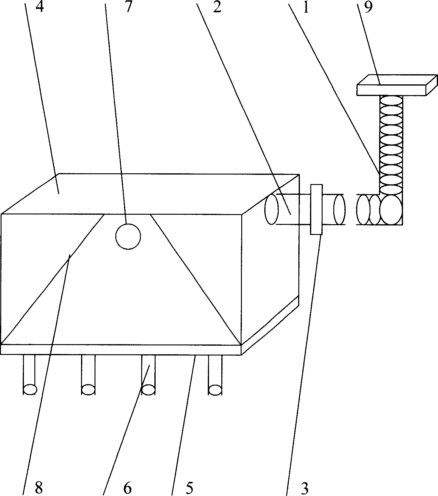
[0016] Referring to the accompanying drawings, the water inlet (2) and the water pipe clamp (3) are set on the upper side of the water tank (4) among the figures, and the viscose pad (5) provided at the bottom is connected with the outdoor unit of the air conditioner and the car radiator. The cover or the side cover is connected, and a diverter nozzle (6) is arranged at the bottom of the water tank (4). The upper part of the water tank (4) is provided with an overflow port (7) and a diversion groove (8). The condensed water in the water receiving tray (9) is guided into the water tank (4) through the drain pipe (1), the water inlet (2) and the water pipe card (3), and evenly distributed to the outside of the water tank (4) through the diverter nozzle, and the water tank (4) ) volume, size, the number and the caliber of the flow nozzle (6) are directly proportional to the power of the air conditioner when it is working.

[0017] The horizontal height of the setting position of...


PUM


Abstract

An air conditioner condensate split flow box includes: the drain pipe, the water inlet, the water pipe clip, the water tank, the viscose cushion, the split flow nozzle, the outgate, the diversion launder and the defrosting pan. Its characteristic are: there sets the viscose cushion at the bottom or on side of the water tank, it makes the water tank fix on the air conditioner outdoor machine , the radiator's cover or side cover through the viscose cushion, upside of the water tank there sets the water inlet and the water pipe clip, the condensate water in the defrosting pan enters the water tank which is inducted by the drain pipe, the water inlet and the water pipe clip, then it equally distributes to outside of water tank through the split flow nozzle which is set at the bottom of water tank's one side, the condensate water's drop direction changes because of the suction of fan, then it adsorbs on the carbon fin, it makes use of the theory that the condensate water volatilizes and radiates heat when happens to heat or wind to avoid the effect that the condensate water's directly discharge brings to the ground, the metope and the passerby, it raises the fin efficiency, lowers the energy consumption and prolongs the compressor's life-span. We can choose water tank's capacity, size and the amounts of the split flow nozzle according to the air conditioner's power. We also can choose water tank material according to the customer's demand.

Description

Technical field: [0001] The invention relates to the environmental protection treatment of condensed water of an air conditioner. More specifically, it is a technical idea that is mainly used to reduce or eliminate the damage to the ground, walls and pedestrians caused by the direct discharge of condensed water from the air conditioner, improve the heat dissipation efficiency of the air conditioner, reduce energy consumption, and extend the service life of the compressor . Background technique: [0002] With the development of social economy and the improvement of people's requirements for environmental temperature comfort, air conditioners are becoming more and more popular. The working time and range of air conditioners have greatly increased, and the total energy consumption has increased rapidly year by year. In various countries and regions, office workers, family members, and car drivers increasingly rely on air conditioners to adjust the temperature in order to maint...

Claims


Application Information

Patent Timeline
IPC IPC(8): F24F13/22
Inventor 周仲平
Owner 周仲平
Why Eureka
Try Eureka