
Method for correcting common-mode wavefront sensor calibration in adaptive optical system

A technology of wavefront sensor and adaptive optics, which is applied in the field of calibration, can solve the problems of cumbersome process, cost, and high cost, and achieve the effect of avoiding time waste

Active Publication Date: 2007-01-31
INST OF OPTICS & ELECTRONICS - CHINESE ACAD OF SCI
View PDF1 Cites 12 Cited by
  • Summary
  • Abstract
  • Description
  • Claims
  • Application Information

AI Technical Summary

Problems solved by technology

[0004] The technical problem solved by the present invention is: to overcome the disadvantages of cumbersome process, high risk and high cost caused by using two standard parallel cursors to determine the common mode wavefront sensor, and to provide a working optical path in the full optical path aberration correction adaptive optical system The method of calibrating common-mode wavefront sensors under certain conditions can avoid the shortcomings of using strict standard plane waves for calibrating common-mode wavefront sensors, and also avoid the time-consuming calibration process

Method used


Image

  • Method for correcting common-mode wavefront sensor calibration in adaptive optical system
  • Method for correcting common-mode wavefront sensor calibration in adaptive optical system

Examples


Embodiment Construction

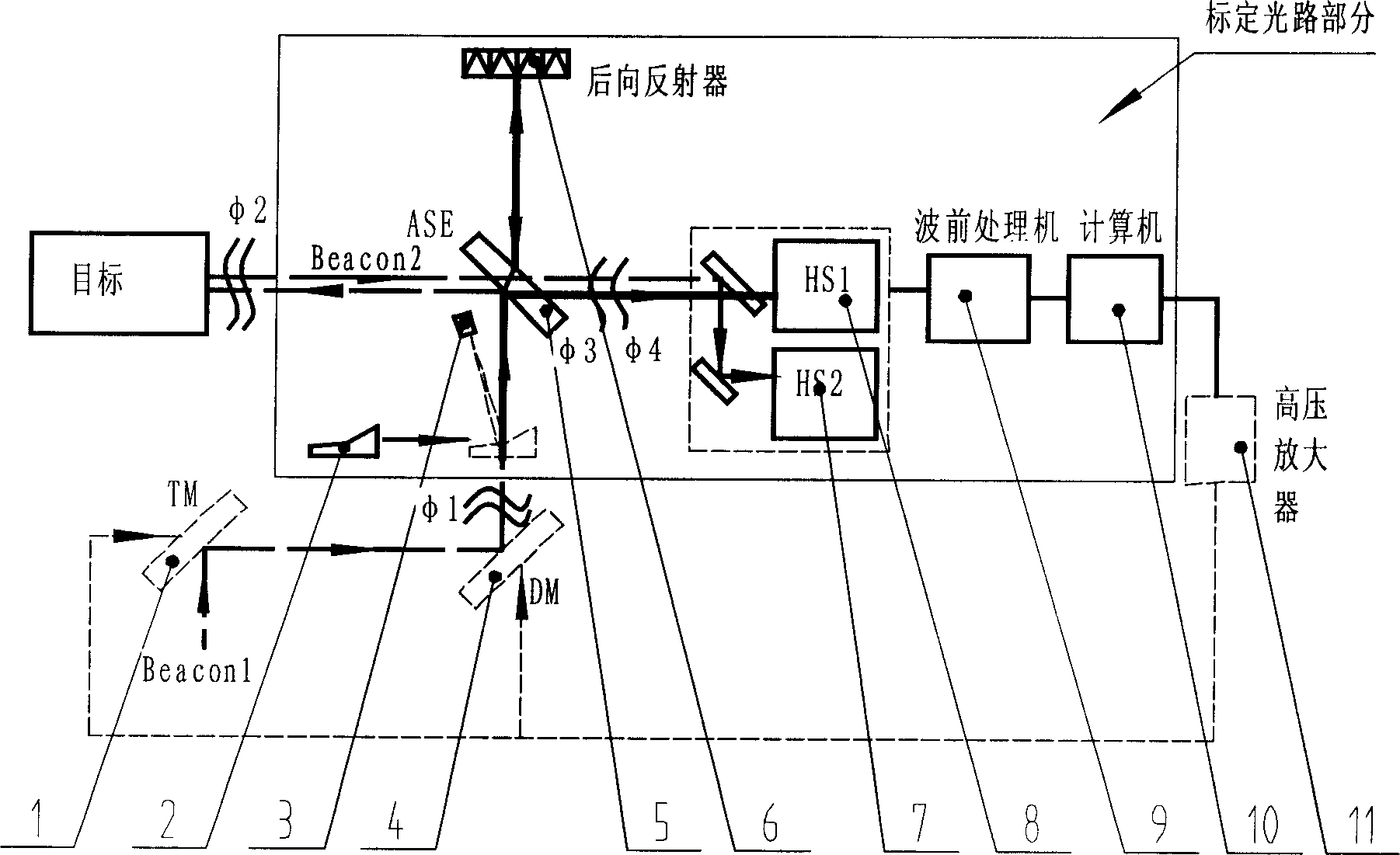
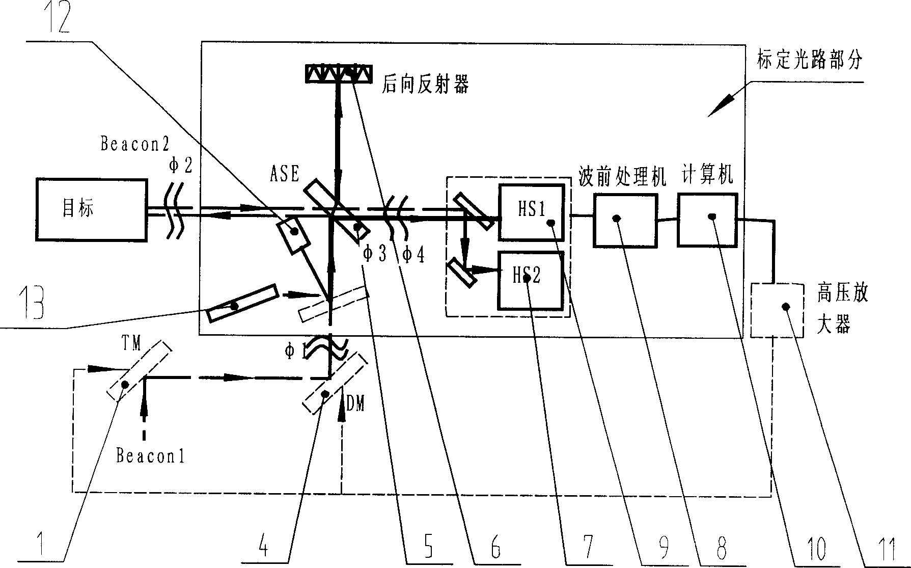
[0013] Such as figure 1 As shown, the system-wide aberration correction adaptive optics system used in the present invention includes a main laser beacon Beacon1, a tilting mirror TM1, a deformable mirror DM4, a common aperture beam splitter 5, and retroreflective devices 6, 7 and 8. Common mode wavefront detector, wavefront processor 9, computer 10, high voltage amplifier 11, atmospheric beacon Beacon2. The method for calibrating a common-mode wavefront sensor described in Technical Embodiment 1 of the present invention is shown in a thin solid line frame, including an off-axis parabolic mirror 2, a calibrating laser 3, a common-aperture beam splitter 5, and retroreflective devices 6, 7, and 8 Composed of a common-mode wavefront detector, a wavefront processor 9, and a computer 10, the light beam emitted by the calibration laser 3 is amplified by the microscope objective lens, and then collimated into parallel light by the introduced off-axis parabolic mirror 2, and the paral...


PUM


Abstract

The invention relates to a common mode wave forward transferring sensor calibrating method in correction self-adapting optical system. The feature is that: inducing parallel light from hole sharing spectroscope under the condition of full light path image difference correcting working light path of self-adapting optical system, the light would be reflected by reflecting array and return to hole sharing spectroscope, and reflecting to common mode wave forward transferring sensor, meanwhile calibrating two sets of wave front transferring sensors included in common wave forward transferring sensor. The invention saves cost and reduces workload.

Description

technical field [0001] The invention relates to a calibration method of a common-mode wavefront sensor in an all-optical-path aberration-corrected adaptive optical system, in particular to a calibration method that requires less parallelism and aberration of the calibration light source, saves calibration time, and reduces moving common-mode sensors. Risks posed by sensors, and a cost-effective calibration method. Background technique [0002] The adaptive optics system is mainly composed of three parts: wavefront detector, wavefront corrector and wavefront controller. The wavefront detector detects the aberration wavefront information in real time, and the wavefront controller converts the signal detected by the wavefront detector into the control signal of the wavefront corrector through the control algorithm, and drives the wavefront corrector to change the shape of the wavefront , to achieve real-time correction of wavefront errors. [0003] The working process of the ...

Claims


Application Information

Patent Timeline
Patent Type & Authority Applications(China)
IPC IPC(8): G02B27/00G01J9/00
Inventor 胡诗杰许冰陈善球
Owner INST OF OPTICS & ELECTRONICS - CHINESE ACAD OF SCI
Learn More