Rope brake system of elevator by using cam

A wire rope and brake technology, which is applied to elevators, lifts, transportation and packaging in buildings, etc., can solve problems such as troubles in on-site installation operations and difficulties in installation operations.

Inactive Publication Date: 2007-01-31
KISAN INFORMATION SYST
View PDF2 Cites 9 Cited by
  • Summary
  • Abstract
  • Description
  • Claims
  • Application Information

AI Technical Summary

Problems solved by technology

Therefore in order to insert the wire rope into the lining between the fixed plate 51 and the movable plate 52, not only need to disassemble the partition plate 56 and remove the spring, but also need to remove many parts such as the movable plate 52, and because the aforementioned movable plate 52 The actuating lever linked with the cam in front of the fixed plate 51 is installed on t

Method used


Image

  • Rope brake system of elevator by using cam
  • Rope brake system of elevator by using cam
  • Rope brake system of elevator by using cam

Examples


Embodiment Construction

[0038] The present invention will be further described below in conjunction with the accompanying drawings.

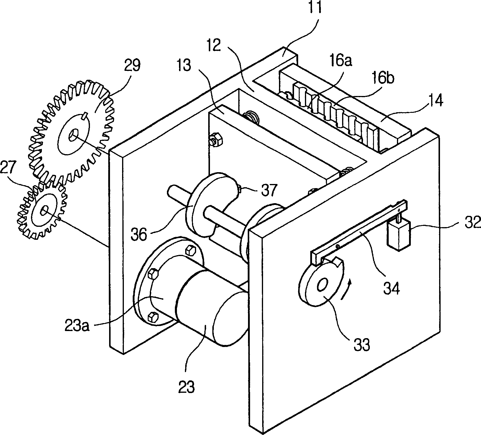
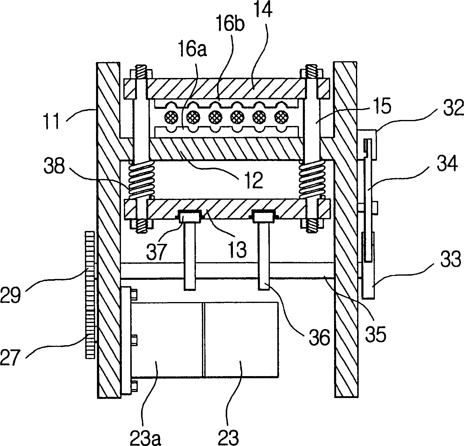
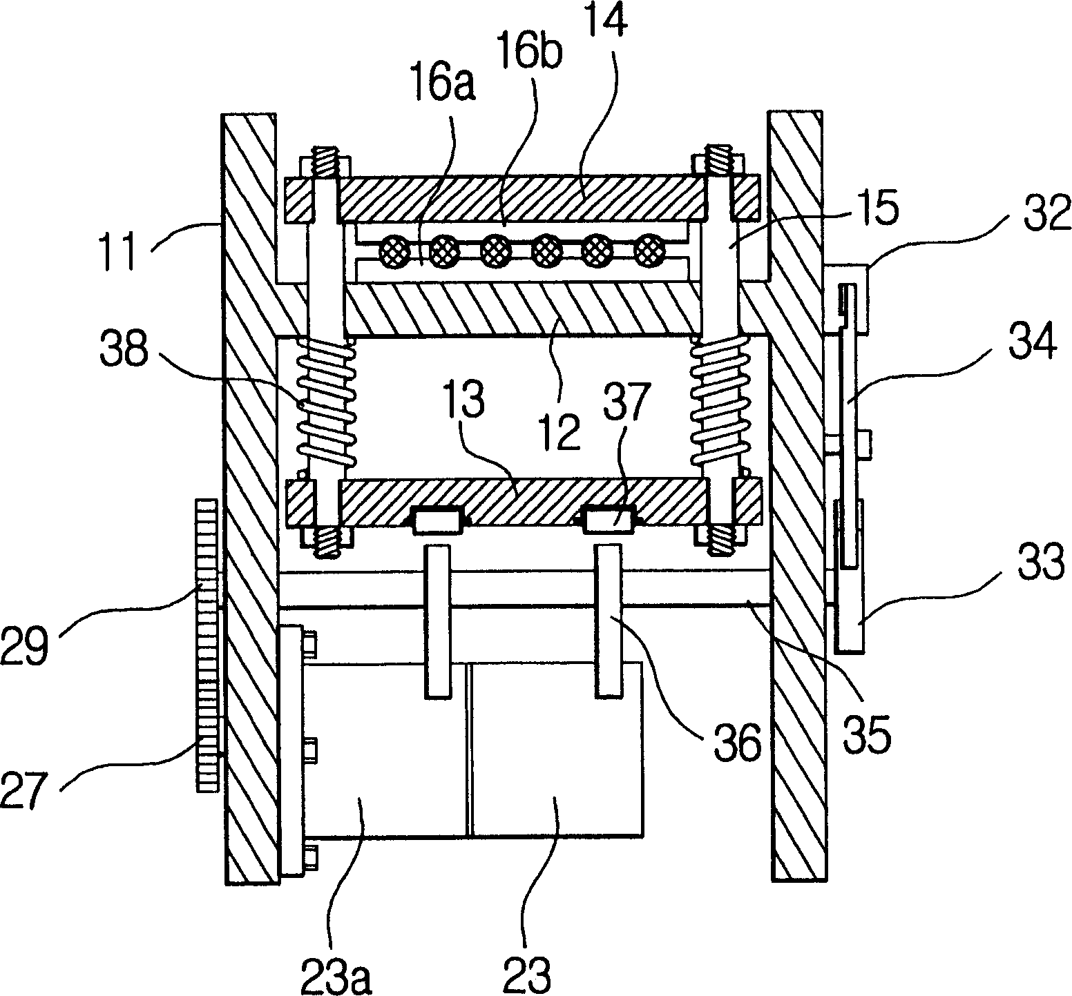
[0039] figure 1 It is a perspective view of the elevator wire rope brake according to the first embodiment of the present invention, figure 2 and image 3 is its floor plan. The structure of the present invention will be further described below in conjunction with the foregoing drawings.

[0040] The left and right boards 11 in the housing are located at both ends of the fixing board 12 and vertically integrated with the fixing board 12 to form an "H"-shaped frame.

[0041] The guide shaft 15 passes through the aforementioned fixed plate and can carry out sliding movement; the movable plate 13 and the movable plate 14 are respectively fixed on the two ends of the aforementioned guide shaft 15; A compression spring 38 is sleeved on the guide shaft 15 to accumulate compression force when the movable plate 13 moves toward the fixed plate 12 .

[0042] Camshaft 35 i...


PUM


Abstract

Disclosed is a rope braking apparatus for an elevator, which operates, by using cams, lining plates for braking rope of the elevator. In the apparatus, at the moment eccentric cams (36) secured to a camshaft (35) are rotated and pass a top dead center, with a trigger lever (34) preventing rotation of the camshaft (35), a state of waiting an emergency brake signal (that is, a normal running state) is maintained. If an emergency situation takes place, as an actuator (32) actuates the trigger lever (34) and compressed springs (38) are returned to their original state, a second movable plate (14) is moved toward a fixed plate (12) to brake the rope of the elevator. At this time, since reverse rotation prevention means is installed in a driving or driven gear (27, 29), a rotation force applied to the eccentric cams (36) is not transmitted to a motor (23).

Description

technical field [0001] The present invention relates to an elevator wire rope brake, especially one that can act in parallel with the running brake (the brake applicable when the elevator is running at normal speed) at ordinary times, and when the elevator is in a stopped state due to the slipping phenomenon of the wire rope, it slowly descends or When the elevator runs faster than the normal speed, the movable plate with brake pads (Brake Lining) will be activated, and the traction rope of the elevator will be clamped and locked in an instant, so as to play the auxiliary brake function to prevent the elevator from sliding down or overspeeding, and then Elevator rope brakes to ensure the safe operation of elevators. Background technique [0002] There are many open patents for elevator wire rope brakes with the above-mentioned purpose at present. In Patent No. 0269685 (1999.07.05. Publication) which the applicant has patented, it is disclosed to have a hydraulic pressure ge...

Claims


Application Information

Patent Timeline
IPC IPC(8): B66B11/08
CPCB66B5/185
Inventor 余时洛
Owner KISAN INFORMATION SYST
Why Eureka
Try Eureka