Method for manufacturing laminated core

An iron core and chip technology, which is applied in the manufacture of stator/rotor body, magnetic circuit shape/style/structure, magnetic circuit static parts, etc., can solve the difficulty of improving the productivity of rotor laminated iron core, the decline of productivity, and the complicated product process Achieve excellent electrical performance, improved bending processing characteristics, and excellent forming accuracy

Inactive Publication Date: 2007-01-31
MITSUI HIGH TEC INC
View PDF6 Cites 11 Cited by
  • Summary
  • Abstract
  • Description
  • Claims
  • Application Information

AI Technical Summary

Problems solved by technology

Therefore, the process of manufacturing the laminated rotor core into a complete product is complicated, thereby causing a decrease in productivity.
[0024] In the above method of manufacturing a rotor laminated core, since the corresponding rotor core pieces D are formed into a ring shape by being wound one by one, it is difficult to increase the productivity of a rotor laminated core having a predetermined number of rotor core pieces D therein.

Method used


Image

  • Method for manufacturing laminated core
  • Method for manufacturing laminated core
  • Method for manufacturing laminated core

Examples


no. 1 example

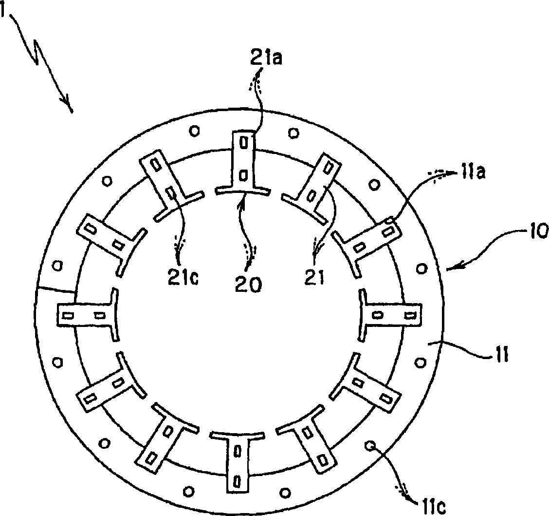
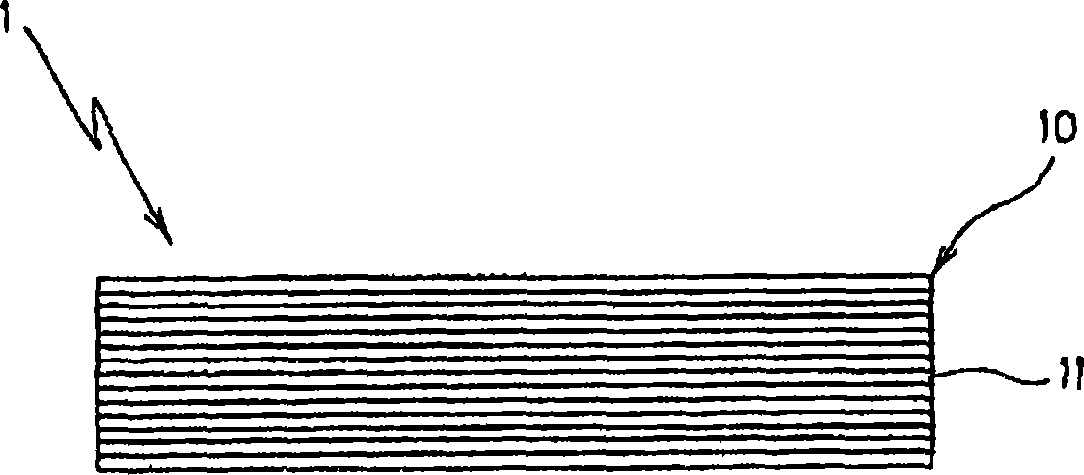
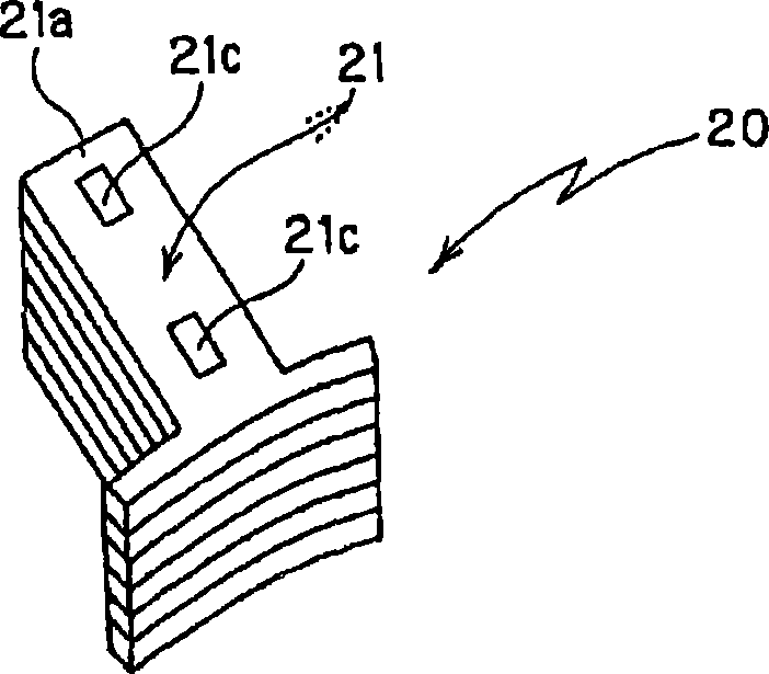
[0186] 1 to 7 show a method of manufacturing a stator laminated core according to the invention. The laminated iron core 1 manufactured according to the present invention includes a laminated yoke body 10 having a belt shape and a predetermined number of laminated magnetic bodies 20, 20 ... (12 in total in the first embodiment), which are coupled to the interior of the laminated yoke body 10. on the circumference edge.

[0187] As will be described later, the laminated yoke body 10 is constituted by winding and laminating a strip-shaped yoke core piece 11 formed by punching a strip-shaped steel plate (metal plate), which has a spiral shape and is coupled in a caulked manner (caulking lamination). Laminated strip steel plates. A predetermined number of concave connection portions 11a, 11a, . . . (12 in total in the first embodiment) are formed on the inner peripheral edge of the laminated yoke body 10. Reference numeral 11c in the figure denotes a caulking portion formed in t...

no. 2 example

[0219] 10 and 11 show a method of manufacturing a stator laminated core according to a second embodiment of the present invention.

[0220] The method according to the second embodiment is substantially similar to the method of the first embodiment described above with reference to Figs. 1 to 9, except that the details of the process of forming a laminated yoke 10' are different from those described above. The stator laminated core manufactured according to the first embodiment is basically similar to the stator laminated core 1 shown in Figs. 1 to 9, except that the partial shape of the laminated yoke 10' is different.

[0221] In the method of manufacturing a stator laminated core according to the second embodiment, first, as Figure 10A As shown, a strip-shaped yoke chip 11' is formed by punching an unshown electrical steel sheet (metal plate).

[0222] The strip-shaped yoke core piece 11' has a shape in which the yoke as a finished stator laminated core is developed in a ...

no. 3 example

[0235] 12 to 17 show a method of manufacturing a stator laminated core according to a third embodiment of the present invention. The laminated iron core 1 manufactured according to the third embodiment includes a laminated yoke body 10 having a ring shape and a predetermined number of laminated magnetic bodies 20, 20... (12 in total in the third embodiment), which are coupled to the laminated yoke body 10. on the inner circumference of .

[0236] As will be described later, the laminated yoke body 10 is constituted by winding and laminating a strip-shaped yoke core piece 11 formed by punching a strip-shaped steel plate (metal plate), which has a spiral shape and is coupled in a caulked manner (caulking lamination). Laminated strip steel plates. A predetermined number of concave connection portions 11a, 11a, . . . (12 in total in the third embodiment) are formed on the inner peripheral edge of the laminated yoke body 10. Reference numeral 11c in the figure denotes a caulking ...


PUM


Abstract

A method for manufacturing a laminated core comprising a step of punching a metal plate to form a stripe yoke core piece having a shape like a linearly developed yoke of a laminated core and having a coupling recess at the peripheral edge corresponding to the inner circumference, a step of winding and laminating the stripe yoke core pieces spirally and caulking them to form a yoke laminate, a step of punching a metal plate to form a pole core piece having a coupling protrusion at the root end, a step of laminating a predetermined number of pole core pieces and caulking them to form a magnetic pole laminate, and a step of winding a wire on the magnetic pole laminate, then fitting the coupling protrusion in the coupling recess, and thus coupling the yoke laminate and the magnetic pole laminate.

Description

technical field [0001] The present invention relates to a method of manufacturing a laminated iron core, and more particularly, to a method by winding and laminating strip-shaped inner sheets in a helical manner and coupling the strip-shaped inner sheets to each other in a caulking manner , to manufacture a laminated core. Background technique [0002] Large-sized laminated cores are used to construct laminated cores in rotating electric machines that generate high power. Since manufacturing a large-sized laminated core such as a stator laminated core requires a large-sized manufacturing device (molding device), this leads to an increase in cost. Furthermore, since when a large-sized stator core sheet is formed by punching, a wide sheared portion is generated from the inside. Consequently, the material efficiency of the chip blank is significantly reduced. [0003] In order to solve the above-mentioned problems, a method of manufacturing a stator laminated core has been p...

Claims


Application Information

Patent Timeline
Patent Type & Authority Applications(China)
IPC IPC(8): H02K15/02H02K1/18
Inventor 三井孝昭藤田胜房
Owner MITSUI HIGH TEC INC
Why Eureka
Try Eureka