
Novel wire-cutting lifting mechanism

A lifting mechanism and wire cutting technology, applied in the field of electrical processing, can solve the problems of unsuitability for mass production, slow lifting speed control, low positioning accuracy, etc., to improve cutting accuracy and slicing quality, stable operation process, and lifting speed. quick effect

Inactive Publication Date: 2011-11-02
东莞汉为智能技术有限公司 +1
View PDF7 Cites 9 Cited by
  • Summary
  • Abstract
  • Description
  • Claims
  • Application Information

AI Technical Summary

Problems solved by technology

[0002] With the rapid development of society, whether it is the modern electronics industry or the photovoltaic industry, the use form of its end products is thin slices, and the quality of its slices depends on the accuracy of slice cutting. However, many existing wire cutting machines are not satisfactory. At present, the length of the arm of the existing cutting machine extending out of the body is constantly changing. Without any mandatory protective measures, the vibration generated by the operation of the cutting machine will cause deviations during cutting, which will affect the quality and cutting accuracy of the slices.
[0003] The traditional wire-cutting upper wire frame is lifted by a hand screw to lift the upper wire frame fixed to the column to cut workpieces of different thicknesses, but the manual operation is realized by the handwheel. The operator brings a lot of labor intensity, and the manual operation has low precision and slow speed, which is not suitable for mass production. Although the lifting mechanism of some cutting machines is composed of guide rails and sliding rods, this structure needs to be tested for single-piece installation , its structure is relatively complex, the control of lifting speed is relatively slow, the accuracy of positioning is low, and it is inconvenient to manufacture and install

Method used


Image

  • Novel wire-cutting lifting mechanism
  • Novel wire-cutting lifting mechanism
  • Novel wire-cutting lifting mechanism

Examples


Embodiment Construction

[0019] In order to further understand the features, technical means, specific objectives and functions achieved by the present invention, and to analyze the advantages and spirit of the present invention, a further understanding of the present invention can be obtained through the following detailed description of the present invention in conjunction with the accompanying drawings and specific embodiments.

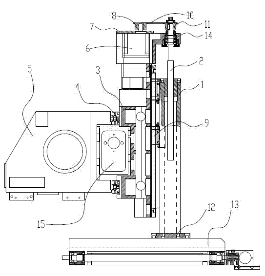
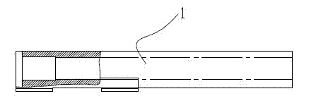
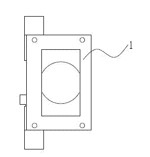
[0020] As shown in the accompanying drawings of the description, the present invention is provided with a lifting guide rail 1, the lifting guide rail 1 is an outer internal hollow structure, and the hollow part in the lifting guide rail 1 is provided with a lifting screw pair 2, and the lifting screw rod The top of the auxiliary 2 is connected to the lifting screw sprocket 11, and the lifting bearing seat 14 is arranged below the lifting screw sprocket 11, and the lifting bearing seat 14 is socketed on the periphery of the lifting screw rod; the lifting guide rail 1 is sock...


PUM


Abstract

The invention discloses a novel wire-cutting lifting mechanism, which comprises a lifting guide rail stable in lifting, high in lifting speed and accurate in positioning. The lifting mechanism is provided with a hollow square lifting guide rail, the hollow part of the lifting guide rail is provided with a lifting screw rod pair, the top ends of the lifting screw rod pair are connected to a lifting screw rod chain wheel, a lifting bearing block is arranged below the lifting screw rod chain wheel, the lifting guide rail is sleeved with an axis-Z linear guide rail pair which is fixedly connected with an axis-X sliding body, the axis-X sliding body is connected with an axis-X linear guide rail pair, an axis-Y sliding body is arranged behind the axis-X sliding body, a lifting motor is arranged above the axis-X sliding body, a motor chain wheel on the upper part of the lifting motor is connected with the lifting screw rod chain wheel through a chain, and the lower end part of the lifting guide rail is connected with a wire feeding rack assembly. The novel wire-cutting lifting mechanism disclosed by the invention has the advantages of high cutting efficiency, improved cutting precision and sliced sheet quality, lightness, high rigidity and reasonableness in stress; and because a gray pig iron casting structure with good stability is adopted, the advantages of light weight and good bending resistance are achieved.

Description

technical field [0001] The invention relates to the field of electrical processing, in particular to a novel wire cutting lifting mechanism. Background technique [0002] With the rapid development of society, whether it is the modern electronics industry or the photovoltaic industry, the use form of its end products is thin slices, and the quality of its slices depends on the accuracy of slice cutting. However, many existing wire cutting machines are not satisfactory. At present, the length of the arm of the existing cutting machine extending out of the body is constantly changing. Without any mandatory protective measures, the vibration generated by the operation of the cutting machine will cause deviations during cutting, which will affect the quality and cutting accuracy of the slices. . [0003] The traditional wire-cutting upper wire frame is lifted by a hand screw to lift the upper wire frame fixed to the column to cut workpieces of different thicknesses, but the man...

Claims


Application Information

Patent Timeline
IPC IPC(8): B23H7/02B23H7/26
Inventor 张国军黄禹李海洲郑振华龚时华赵业强袁勇杨涛
Owner 东莞汉为智能技术有限公司
Learn More