
Cotton candy machine

A technology of marshmallow and syrup, applied in confectionery, confectionary industry, food science, etc., can solve the problems of complicated preparation work, limitation of opening area, limitation of rotating pot volume, etc., and achieve the effect of easy operation and improved workability

Active Publication Date: 2007-02-07
HAPPINET CORP
View PDF2 Cites 5 Cited by
  • Summary
  • Abstract
  • Description
  • Claims
  • Application Information

AI Technical Summary

Problems solved by technology

This produces the problem that the opening area of ​​the opening for putting in the syrup is limited, and the volume of the rotary pot is limited.
Therefore, especially when sugar balls are used as a material, it is necessary to break the sugar balls into small pieces of the required size before putting them into the rotary pot, and use the sugar balls as a material, which sometimes requires complicated preparations.

Method used


Image

  • Cotton candy machine
  • Cotton candy machine
  • Cotton candy machine

Examples


Embodiment 1

[0029] Hereinafter, Embodiment 1 of the cotton candy machine of the present invention will be described with reference to the drawings.

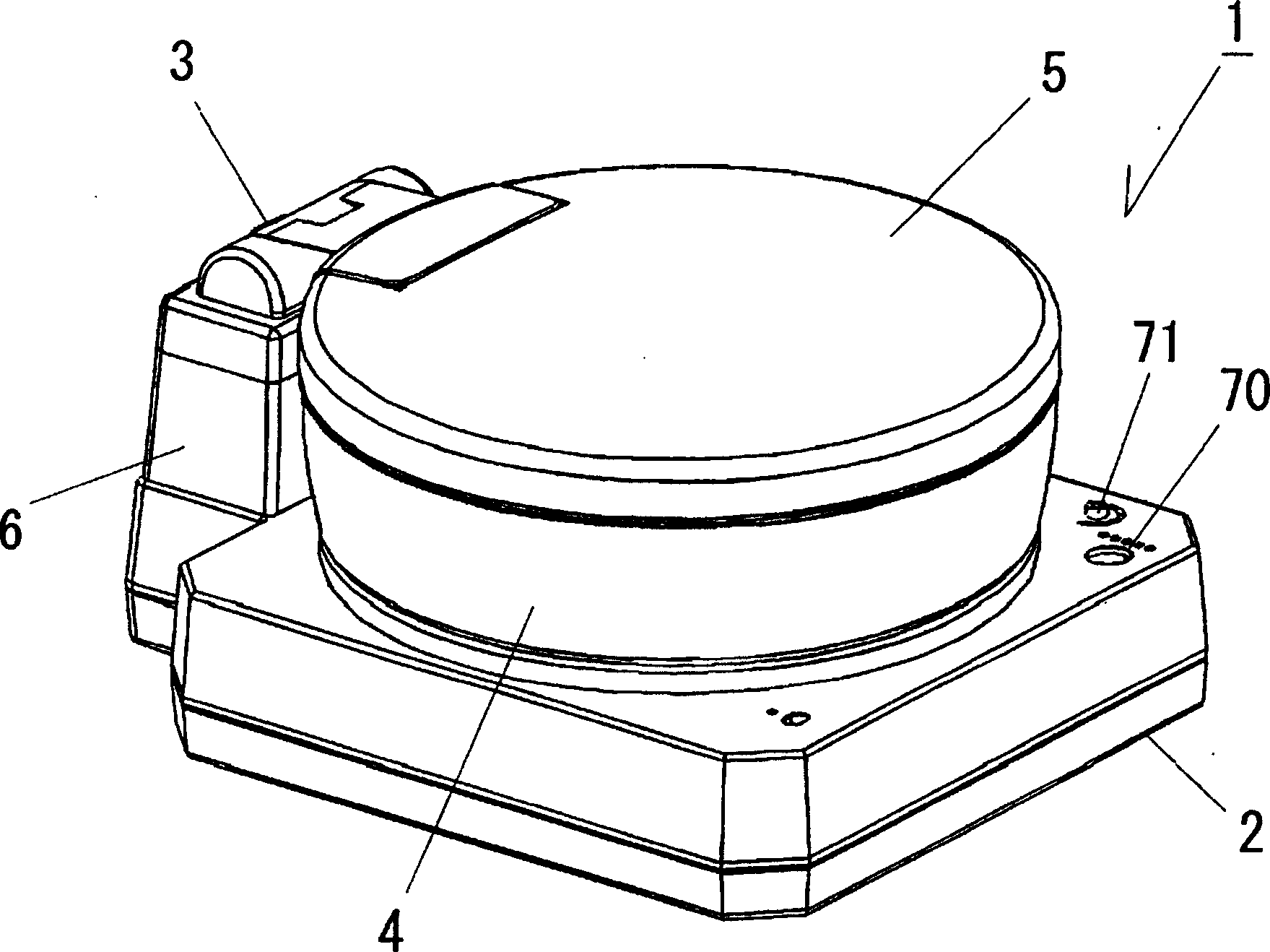
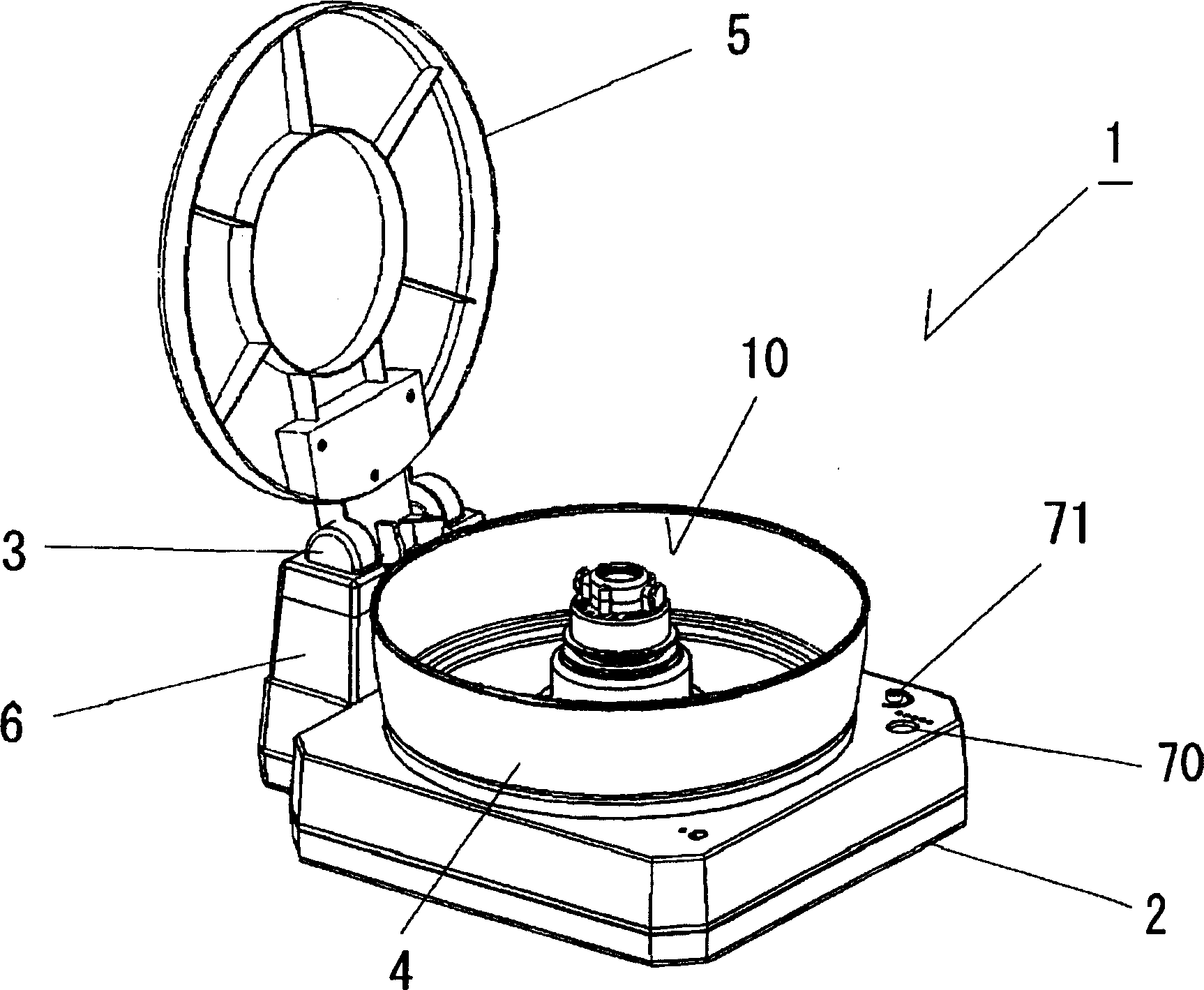
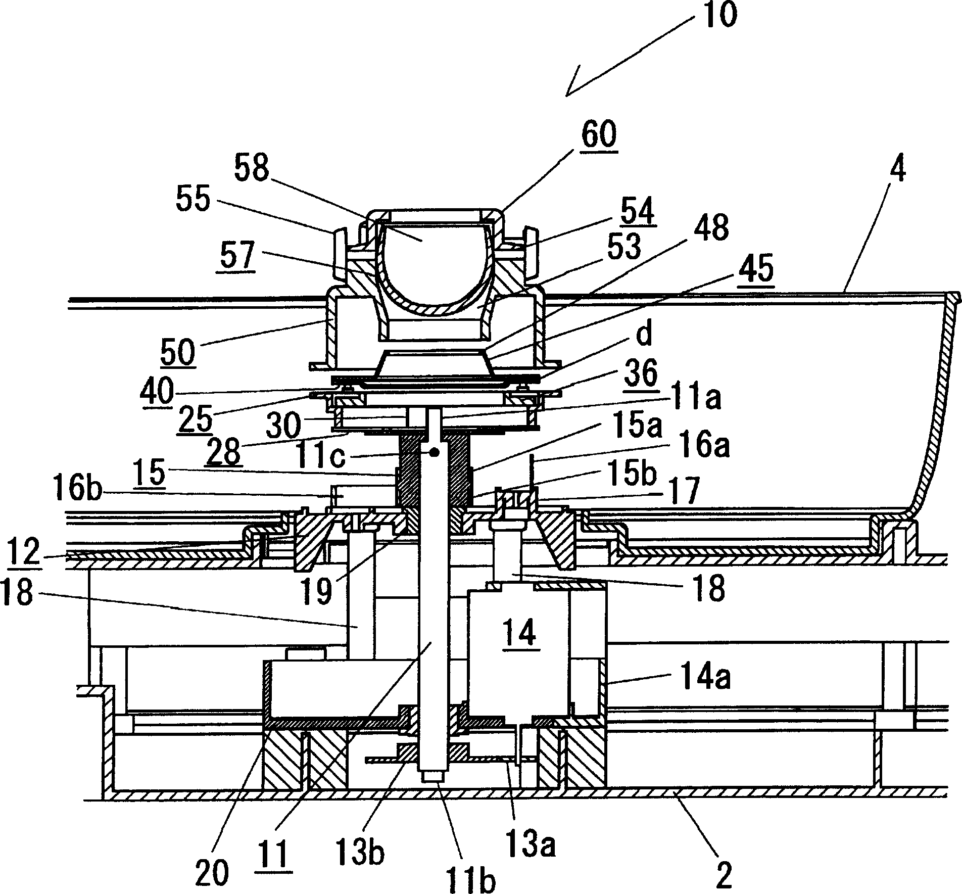
[0030] like figure 1 , figure 2 As shown, the cotton candy machine 1, the cotton candy production part 10 has a base 2 arranged in the center, and an annular tray 4 installed around the cotton candy production part 10 on the base 2. In this configuration, thread-like syrup is scattered outward from the cotton candy manufacturing unit 10, and the syrup can be wound up in the tray 4 with disposable chopsticks or the like.

[0031] Furthermore, a support portion 6 including a hinge member 3 is connected to the left side of the base 2 . Furthermore, a disk-shaped cover 5 is connected to this hinge member 3 . Then, by the hinge member 3, by making the disc-shaped cover 5 fall substantially horizontally, or stand up substantially vertically, the cotton candy machine 1 becomes the covered state in which the inside of the tray 4 is covered (refe...

Embodiment 2

[0064] The marshmallow manufacturing unit 10a having a configuration different from the above will be described. In addition, the same symbols are assigned to the same configuration as in the first embodiment, and the description thereof will be simplified or omitted.

[0065] like Figure 7 , Figure 8 As shown, in Embodiment 2, the winding reel placement table 85 , the winding reel 36 , the melting tray 40 , the cover 45 , and the protective case 95 are also mounted on the horizontal base 28 . However, in this embodiment, the mechanism for fixing the position of these components on the horizontal base 28 is different from that of the first embodiment. Hereinafter, this mechanism will be described.

[0066] like Figure 8 As shown, the reel placement platform 85 has an open ring shape in its center, and a section 90 is provided on its inner surface. In addition, three supporting parts 86 that pivotally support claws 87 to be described later are provided around the upper ...


PUM


Abstract

To provide a cotton candy machine that is useful especially when using candy balls as a cotton candy material. The cotton candy maker has the following structure: a horizontal base plate 28 is placed on the upper end 11a of a rotary axis 11; a screw rod 30 is placed at a position deviated away from the axis line of the rotary axis 11 in a standing fashion; respective engagement holes 25a, 36a, 40a, 45a, 50a of a bobbin-receiving board 25, a bobbin 36, a melting tray 40, a lid body 45 and a protection cover body 50 are inserted into the screw rod 30 so as to tighten the bobbin receiving board 25, the bobbin 36, the melting tray 40, the lid body 45 and the protection cover body 50 in a laminated state.

Description

technical field [0001] The invention relates to a cotton candy machine for making cotton candy. Background technique [0002] In the conventional cotton candy machine, sugar is put into a bottomed rotary pot, and the rotary pot is heated by a heater to melt the sugar until it becomes thick. Marshmallows are produced by scattering molasses (for example, refer to Patent Document 1). Here, the structure of the cotton candy machine shown in Patent Document 1 will be briefly described. In this cotton candy machine, a vertical fixed shaft 6 connected to a power mechanism 4 is vertically inserted through the center of a rotary pan 10 into which sugar is put. With this configuration, when the vertical fixed shaft 6 rotates at a high speed, the rotary pan 10 also rotates at a high speed. [0003] In addition, as a material of marshmallows, a configuration using finished sugar balls has also been proposed (for example, refer to Patent Document 2). This composition of using finished...

Claims


Application Information

Patent Timeline
Patent Type & Authority Applications(China)
IPC IPC(8): A23G3/02
CPCA23G3/10
Inventor 小池不二林芳幸
Owner HAPPINET CORP
Learn More