Optical switch reversing device for test of multiple light jaws equipment

A switching device and equipment testing technology, applied in the field of communication, can solve problems such as low efficiency and difficulty in improving test efficiency, and achieve the effects of convenient operation, improved test efficiency, and low cost

Active Publication Date: 2007-02-07
ELECTRIC POWER SCI RES INST OF STATE GRID XINJIANG ELECTRIC POWER
View PDF0 Cites 24 Cited by
  • Summary
  • Abstract
  • Description
  • Claims
  • Application Information

AI Technical Summary

Problems solved by technology

[0005] 1. If figure 1 As shown in the figure, connect the bit error testing equipment to each optical port separately, and test each optical port separately, so that it can be judged whether each optical port is normal, but since each optical port needs to be tested separately, its efficiency is very low
[0006] 2. If figure 2 As shown, connect the bit error test equipment to the sending and receiving ends of the first and last optical ports, connect the receiving a

Method used


Image

  • Optical switch reversing device for test of multiple light jaws equipment
  • Optical switch reversing device for test of multiple light jaws equipment
  • Optical switch reversing device for test of multiple light jaws equipment

Examples


Embodiment Construction

[0026] The optical switching device of the present invention will be further described below in conjunction with the accompanying drawings.

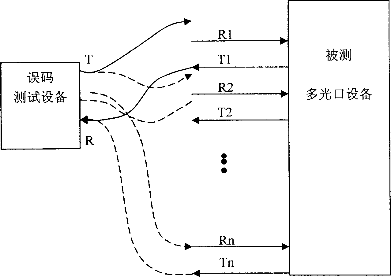
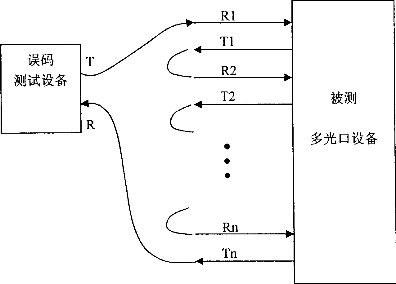
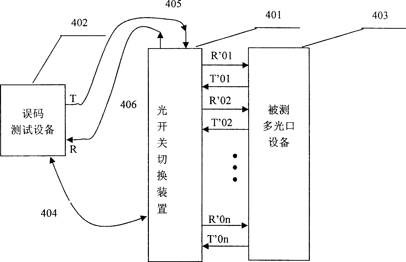
[0027] The optical switch switching device 401 of the present invention, as shown in 3, is configured to multi-connect each optical port of a multi-optical port device 403 to be tested; Test equipment 402; the optical switch switching device 401 includes a main controller 500 and an optical switch array unit 600, the main controller 500 and the optical switch array unit 600 together form an optical switch switching device, the core of which is the optical switch array The interconnection mode between the unit 600 and the optical switching element. Among them, the optical switch switching device is interconnected with the bit error testing equipment through the optical fibers 405 and 406 in a certain communication mode 404, and is interconnected with the tested multi-optical port equipment through the optical fibers. The main controller ...


PUM


Abstract

The invention relates to a light switcher used to test multi-light-port device, wherein it is arranged between one error bit tester and one tested multi-light-port device; it comprises one main controller and a light switch array unit; said main controller comprises a processor, a communication interface, a driving circuit and a programmable logic unit; the main controller is used to communicate between the light switch and the error bit tester, to arranged the light switch of light switch array unit; said light switch array unit has several light switches, whose setting is controlled by the main processor uses driving circuit to set the control pin of each light switch. The invention can be connected to extender, to improve the testing efficiency, with simple operation and low cost.

Description

technical field [0001] The invention belongs to testing equipment in the field of communication, in particular to an optical switch switching device which can be used for testing optical port error code functions of multi-optical port equipment. Background technique [0002] Due to the large transmission capacity of optical fiber, the optical transport network with optical fiber as the transmission carrier has become one of the basic networks of the entire communication network. At present, a large number of multi-optical port devices are used on the Internet. Typical multi-optical port devices include SDH transmission systems based on time division switching. Equipment and DWDM dense wavelength division system equipment based on wavelength switching. At the same time, for system equipment with optical ports, due to the increase in transmission capacity, there are more and more optical ports at each end of the equipment. In terms of DWDM dense wavelength division system equi...

Claims


Application Information

Patent Timeline
IPC IPC(8): H04B10/08H04B10/12H04B10/07
Inventor 吴德荣王吓弟孟凡伟丁国兴
Owner ELECTRIC POWER SCI RES INST OF STATE GRID XINJIANG ELECTRIC POWER
Why Eureka
Try Eureka