Plastic pipe and its diversion method

A water divider and a practical technology, applied in the direction of pipes, pipe components, branch pipelines, etc., can solve the problems of high production cost, complex structure, inconvenient use, etc., and achieve the effect of low cost, convenient operation and simple structure

Inactive Publication Date: 2007-02-14
GUANGDONG LIANSU TECH INDAL
View PDF1 Cites 0 Cited by
  • Summary
  • Abstract
  • Description
  • Claims
  • Application Information

AI Technical Summary

Problems solved by technology

The special water separator for plastic pipes cannot be opened at any position of the pipe, and the pipe needs to be opened in advance, which is inconvenient to use, complicated in structure and high in production cost

Method used


Image

  • Plastic pipe and its diversion method
  • Plastic pipe and its diversion method
  • Plastic pipe and its diversion method

Examples


Embodiment Construction

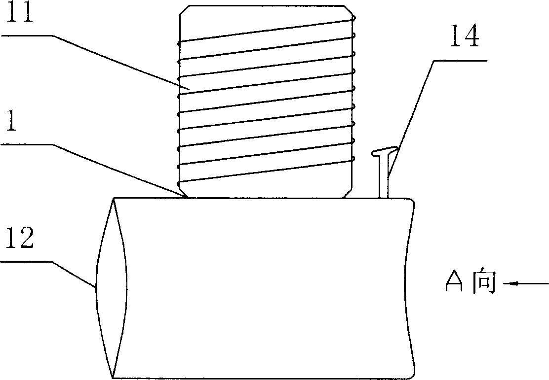
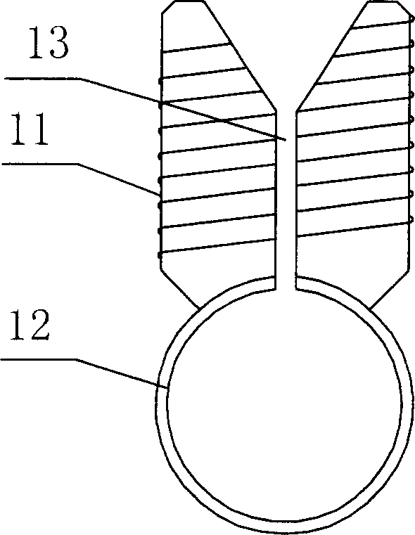
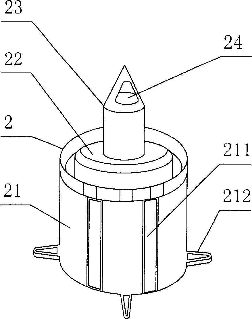
[0018] Figure 1 ~ Figure 4 A water separator for plastic pipes according to the present invention is shown, including a pipe collar 1 and a joint 2 sleeved on the outer wall of the pipe collar 1, wherein the pipe collar 1 includes a longitudinal sleeve 11 and a joint 2 sleeved together. The horizontal casing 12 used to socket the water pipe 3, the longitudinal casing 11 and the horizontal casing 12 are arranged in a "⊥" shape, and the middle part of the longitudinal casing 12 is provided with an open groove 13 parallel to its axis, and the open groove 13 can also be In order to pass through the central axis of the longitudinal casing 11 of the pipe collar 1 and be parallel to the axial direction of the horizontal casing 12, and the upper part is also made with a "V"-shaped gap, and the setting of the opening groove 13 is convenient for the water pipe to be packed into the horizontal casing. The joint 2 includes an outer sleeve 21 sleeved on the outside of the longitudinal sle...


PUM


Abstract

A method for dividing water from plastic pipe includes sleeving water pipe into horizontal sleeve of pipe hoop and connecting connector to longitudinal sleeve of pipe hoop to let external sleeve of connector screw-fixed in longitudinal sleeve of pipe hoop, drilling drill head into water pipe to open a mouth on water pipe for realizing water-dividing purpose. The water-divider for realizing said method is also disclosed.

Description

technical field [0001] The invention relates to a water separator, in particular to a water separator for plastic pipes and a water dividing method thereof. Background technique [0002] In the prior art, new plastic pipes using polypropylene, polyethylene and other pipe materials have begun to be widely used, and the demand for water separators used for centralized control of plastic pipes is also increasing day by day. In the centralized control of the existing plastic pipe water supply pipelines, most of them are controlled by large valves. The pipelines are independent of each other, the system is huge, and the maintenance of the pipelines is difficult. Moreover, it is necessary to open holes in the pipelines before use, and the water separator cannot be used directly. Opening holes for water separation is inconvenient to use, complicated in structure and high in manufacturing cost. Chinese Patent No. 200420107978.X (the application date is November 2, 2004, and the ann...

Claims


Application Information

Patent Timeline
Patent Type & Authority Applications(China)
IPC IPC(8): F16L55/00F16L41/00
Inventor 袁栋平
Owner GUANGDONG LIANSU TECH INDAL
Why Eureka
Try Eureka