

Chain transmission or steering device and the chain or chain wheel used therein
A steering gear, chain drive technology, applied in the direction of belt/chain/gear, drag chain, hanging chain, etc., to avoid line contact, increase the risk of damage to the chain or sprocket, and the effect of large chain traction
- Summary
- Abstract
- Description
- Claims
- Application Information
AI Technical Summary
Problems solved by technology
Method used
Image

Examples
Embodiment Construction
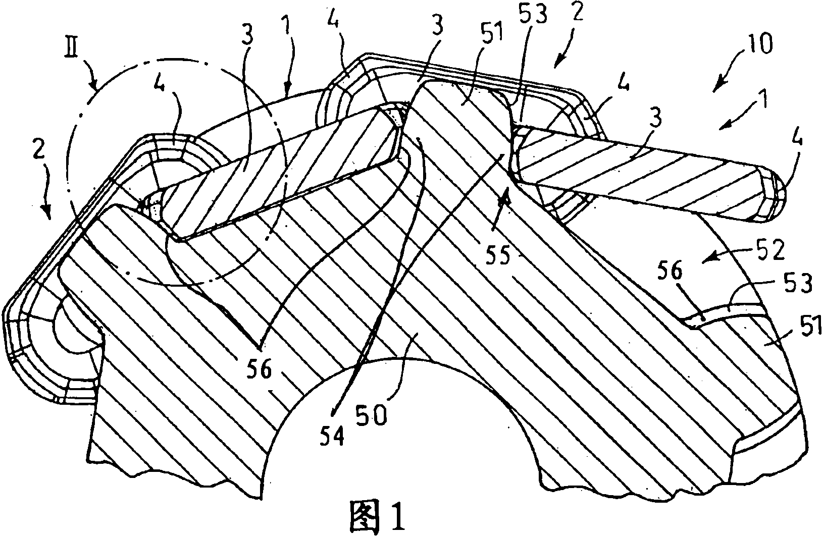
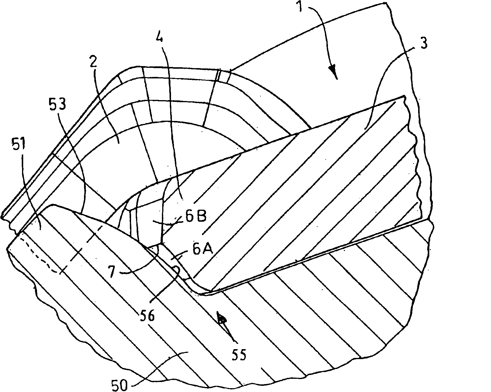
[0025] figure 1Shown are two horizontal links 1 and two vertical links 2 connected to them in a plow chain generally indicated by reference numeral 10, which are designed identically to each other in the illustrated embodiment, And as a die forging, it is composed of two chain link edges 3 parallel to each other and the chain head 4 that connects them and is designed as an arrowhead at the top of the horizontal link 1 and the vertical link 2. exist figure 1 with 2 Shown is the plow chain 10 meshing with the sprocket teeth 51 of a sprocket 50, which is selectively driven in one or the other direction of rotation by means of a drive (not shown further) during operation of the underground plowing plant. The sprocket 50 is provided with chainring pockets 52 between two adjacent sprocket teeth 51 , which are delimited by tooth flanks 53 of the teeth 51 . Here, the device is designed in such a way that the tooth flanks 53 delimiting the chain ring socket 52 are provided with sphe...
PUM
 Abstract
Description
Claims
Application Information