Eureka AIR delivers breakthrough ideas for toughest innovation challenges, trusted by R&D personnel around the world.

Component feeder

A technology for supplying devices and components, applied in the direction of electrical components, electrical components, delivery objects, etc., which can solve the problems of reducing the pasting area, bumps and bumps, and the covering tape cannot be easily discharged.

Inactive Publication Date: 2010-06-09
JUKI CORP
View PDF2 Cites 0 Cited by
  • Summary
  • Abstract
  • Description
  • Claims
  • Application Information

AI Technical Summary

Problems solved by technology

[0009] However, conventional non-adhesive coatings use fluorine or silicone as a matrix to form a concave-convex structure mainly adding spheres such as glass beads to reduce the area to be pasted. Adhesiveness, therefore, unevenness becomes an obstacle, and the covering tape cannot be easily discharged

Method used


Image

  • Component feeder
  • Component feeder
  • Component feeder

Examples


Embodiment Construction

[0025] Hereinafter, embodiments of the present invention will be described in detail with reference to the drawings.

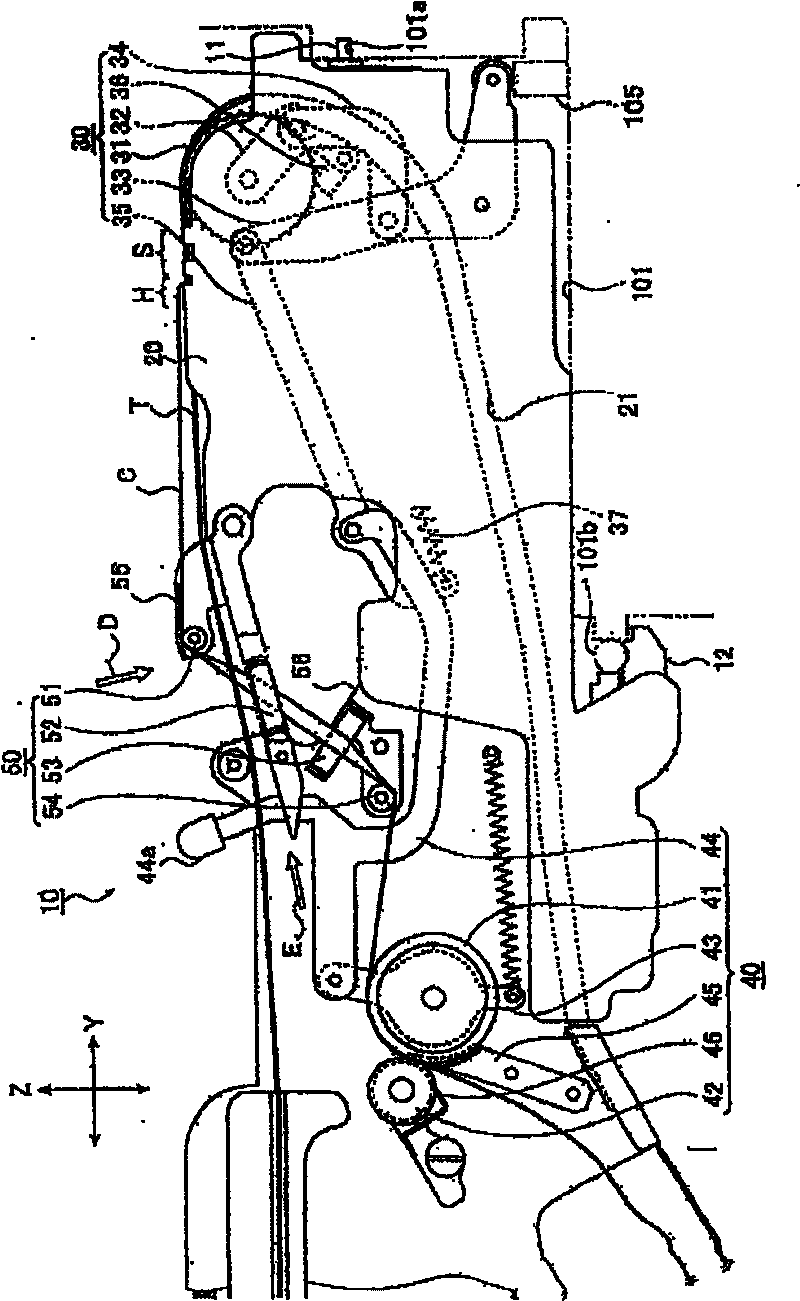
[0026] figure 1 It is a schematic side view showing a part of a parts feeder (parts supplying device) according to one embodiment of the present invention.

[0027] The components feeder 10 of this embodiment is mounted on the above-mentioned feeder magazine by inserting the engaging protrusion 11 into the engaging hole of the feeder magazine provided by the electronic component mounting device (not shown), and is similarly A plurality of parts feeders 10 are installed and used in parallel. figure 1 A part of the front end side of the components feeder 10 mounted on the feeder magazine is shown.

[0028] The parts feeder 10 sequentially feeds out the carrier tape T preliminarily wound on the reel from a reel (not shown) held on the rear end side, and moves toward the front end side along the transport path 21 formed on the frame body 20 . to deliver. Such ...


PUM


Abstract

The invention provides a component feeder can effectively prevent the jamming of a cover tape in a discharge path. A carrier tape wound in advance on a reel held at a specified position is sequentially delivered and transported to the downstream side. A cover tape is peeled off the tape body of carrier tape that has reached a peeling position, and a component stored in the recess of the tape bodyis exposed. Then the component is supplied to the pick up position on the downstream side while the cover tape that has been peeled is wound on a rotor provided on a specified position. The rotor is rotated in synchronous with delivery of the carrier tape. So the cover tape is delivered while applied with tension, and discharged to the downstream side by way of the discharge path on the rotor exitside. A discharge guide provided with a first main surface guide part and a second main surface guide part of which an interval gradually increases from the vicinity of the rotor toward discharging direction, is arranged on the main surface sides of the cover tape discharged to the discharge path.

Description

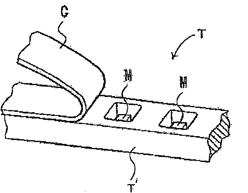
technical field [0001] The present invention relates to a component supply device that supplies a plurality of electronic components to a predetermined position by sequentially feeding out a carrier tape containing many electronic components. Background technique [0002] Conventionally, a carrier tape has an elongated tape main body in which a plurality of recesses are formed at intervals in the longitudinal direction, components are accommodated in each of the recesses, and a cover tape having a sticking portion (adhesive surface) formed thereon is attached to the tape. Take the upper surface of the main body to cover the recess. In addition, the tape feeder is used in such a way that the carrier tape is wound on the reel in advance, and the above-mentioned carrier tape is sequentially sent out and conveyed from the reel, and at the same time, after the cover tape is peeled off from the main body of the carrier tape, after a predetermined The position is taken out of the ...

Claims


Application Information

Patent Timeline
IPC IPC(8): B65H41/00H05K13/02
Inventor 笹本宪一篠崎雅则
Owner JUKI CORP
Why Eureka
Eureka Blog
Learn More