
Spark gap arrestor

A lightning arrester and discharge electrode technology, which is applied in the field of lightning arrester structure, can solve the problems of load circuit power supply blockage, wiring or appliance influence, and inability to stop continuous current, etc., to achieve the effect of suppressing material costs and avoiding cumbersome operations

Inactive Publication Date: 2007-02-21
合资会社CSD
View PDF1 Cites 9 Cited by
  • Summary
  • Abstract
  • Description
  • Claims
  • Application Information

AI Technical Summary

Problems solved by technology

If the continuous current is blocked by an external protection circuit, the power supply to the load circuit is blocked, or the overvoltage protection function is lost because the spark gap arrester is blocked from the power line.
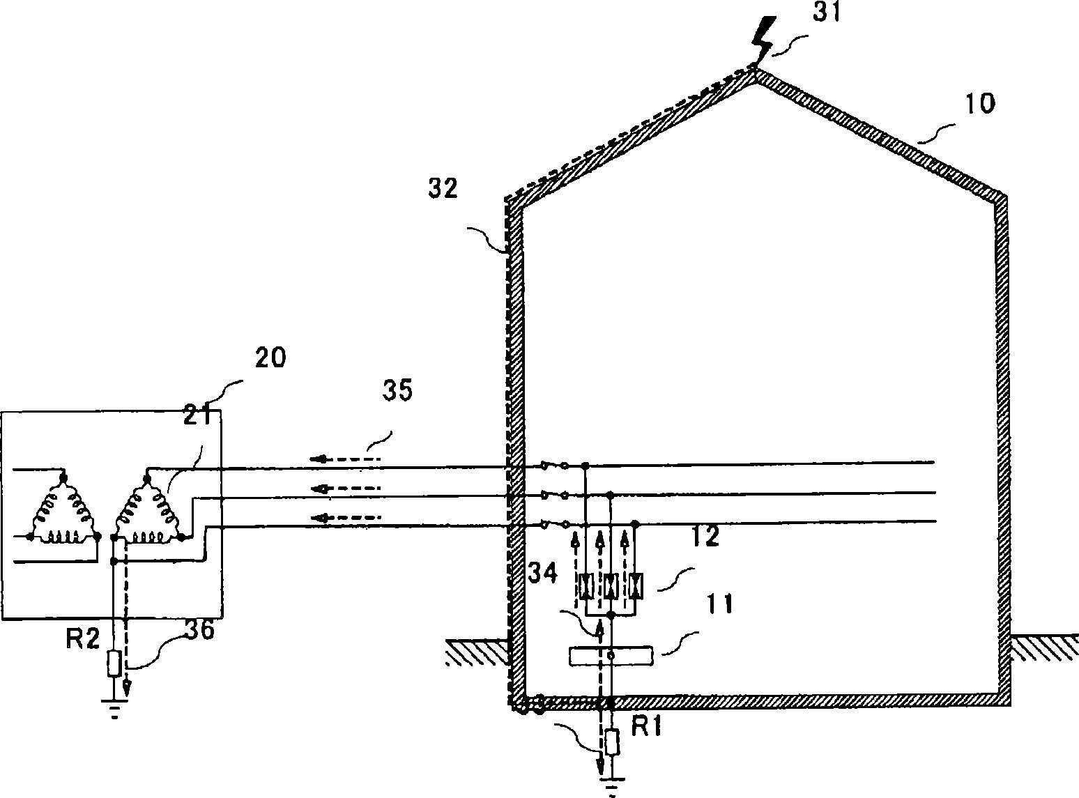
[0019] (2) When a large lightning pulse current flows, the air around the arc discharge path in the air will be heated, ionized and explosively expanded and ejected, affecting the surrounding wiring or appliances
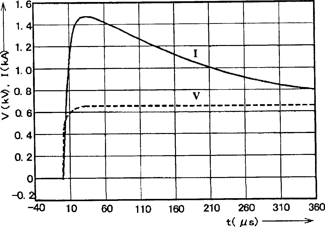
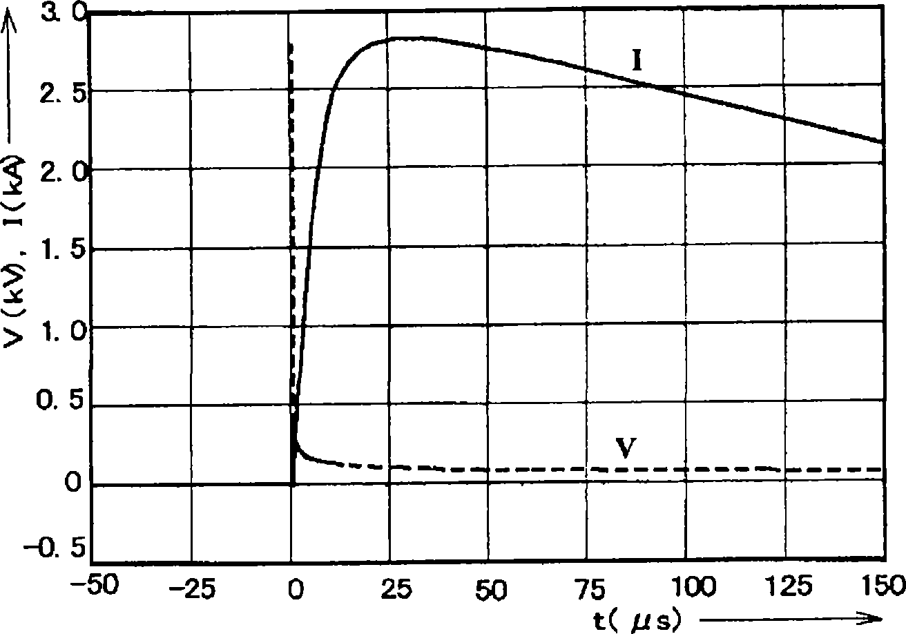
When the pulse current is roughly reduced to 0, if the arc voltage is roughly equal to the power supply voltage, the continuous current will not be generated, but when the arc voltage is the above (U A +U K ) = 60V, it can not stop the continuous current

Method used


Image

  • Spark gap arrestor
  • Spark gap arrestor
  • Spark gap arrestor

Examples


Embodiment Construction

[0056] Below, refer to Figure 7 , Figure 8 The structure and function of the lightning arrester for low-voltage AC power supply circuit of the present invention will be described in detail.

[0057] Figure 7 It is a longitudinal sectional view of a cylinder-enclosed arrester. The components are manufactured and arranged in rotational symmetry with respect to the central axis. The bases of both discharge electrodes are made of copper members 102a and 102b which are common conductors, and the front ends are made of copper tungsten sheets 101a and 101b excellent in heat resistance and arc resistance. The base parts 102a, 102b and the front end parts 101a, 101b are integrated by fitting the convex part of the front part into the concave part of the base part, without performing complicated processes such as welding. The concavo-convex part of the base part and the front part may be reversed combination. The discharge electrode is conical in this embodiment. Instead of thi...


PUM


Abstract

The invention is to realize a spark gap arrestor of encapsulation structure in which a dynamic current is eliminated by increasing the voltage drop independent from an arc current and thereby preventing restrike due to the power supply voltage after passage of a lightning current. In a tubular metallic case containing a spark gap, a plurality of metal rings of magnetic material are arranged as an arc-suppressing plate concentrically with a conical or cylindrical electrode constituting the spark gap. An arc generated when a lightning current passes is guided to the arc-suppressing plate on the outer circumference, and restrike due to the power supply voltage after passage of the lightning current is prevented by an arc voltage appearing on both sides of the arc-suppressing plate.

Description

technical field [0001] The invention relates to a lightning arrester structure for bypassing lightning current and releasing it to the ground, which is set on a low-voltage AC power supply circuit in order to protect electronic equipment sensitive to overvoltage when lightning strikes. Background technique [0002] After the Franklin-type lightning rod was invented in the second half of the 1700s, lightning rods and wires (external lightning protection) were mainly used as lightning protection devices for buildings in about 200 years. This is because, if these conductors are used to receive the lightning strike current and release it to the earth through the grounding electrode in the shortest distance, the disaster can be minimized. But when distribution lines and telephone lines became popular in the early 1900s, the lightning current flowing into the building through these lines or the lightning current flowing into the building's external ground through these lines when ...

Claims


Application Information

Patent Timeline
Patent Type & Authority Applications(China)
IPC IPC(8): H01T4/12H01T1/02H01T1/04
CPCH01T4/12H01T1/04H02H9/06H01T4/00
Inventor 加藤幸二郎
Owner 合资会社CSD
Learn More