
Method of recognizing external adjustment steps

A measure, technology of internal combustion engines, applied in fuel injection control, engine control, machine/engine, etc., can solve problems such as difficulty in changing data

Inactive Publication Date: 2007-02-28
ROBERT BOSCH GMBH
View PDF3 Cites 6 Cited by
  • Summary
  • Abstract
  • Description
  • Claims
  • Application Information

AI Technical Summary

Problems solved by technology

Hierarchical access rights through cryptographic methods are also known, by which the alteration of data stored in the controller is made more difficult

Method used


Image

  • Method of recognizing external adjustment steps
  • Method of recognizing external adjustment steps

Examples


Embodiment Construction

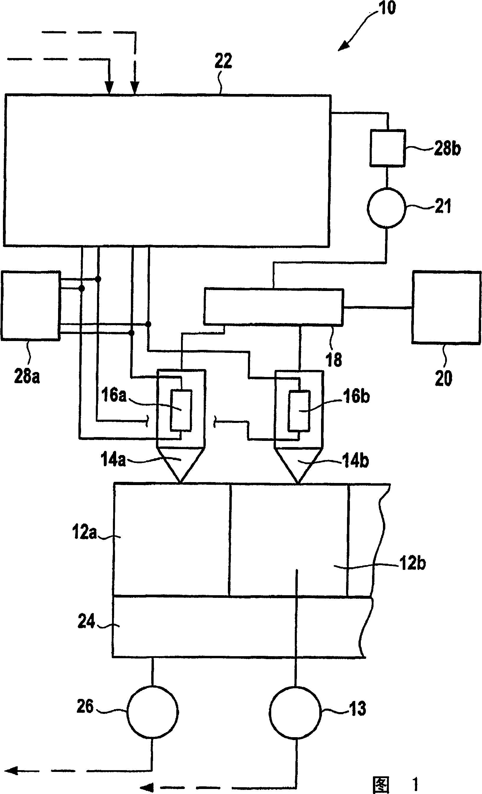
[0015] An internal combustion engine is indicated generally in FIG. 1 by the reference numeral 10 . It is used to drive a car not shown in the picture.

[0016] The internal combustion engine 10 includes a plurality of combustion chambers, of which only those combustion chambers are indicated by reference numerals 12a and 12b in FIG. 1 . The pressure in the combustion chamber 12b is detected by a pressure sensor 13, and the pressure in the other combustion chambers is also deduced from its signal by suitable modules. Each combustion chamber 12a and 12b is associated with a fuel injection nozzle 14a or 14b, which in turn includes a piezoelectric adjusting component 16a or 16b. These components can be used to influence the actuating position of a valve element of an injection group 14 a or 14 b (not shown in FIG. 1 ). The injection of fuel into the combustion chamber is ultimately controlled by the valve element. The injector 14 is connected to a fuel pressure accumulator 18 ...


PUM


Abstract

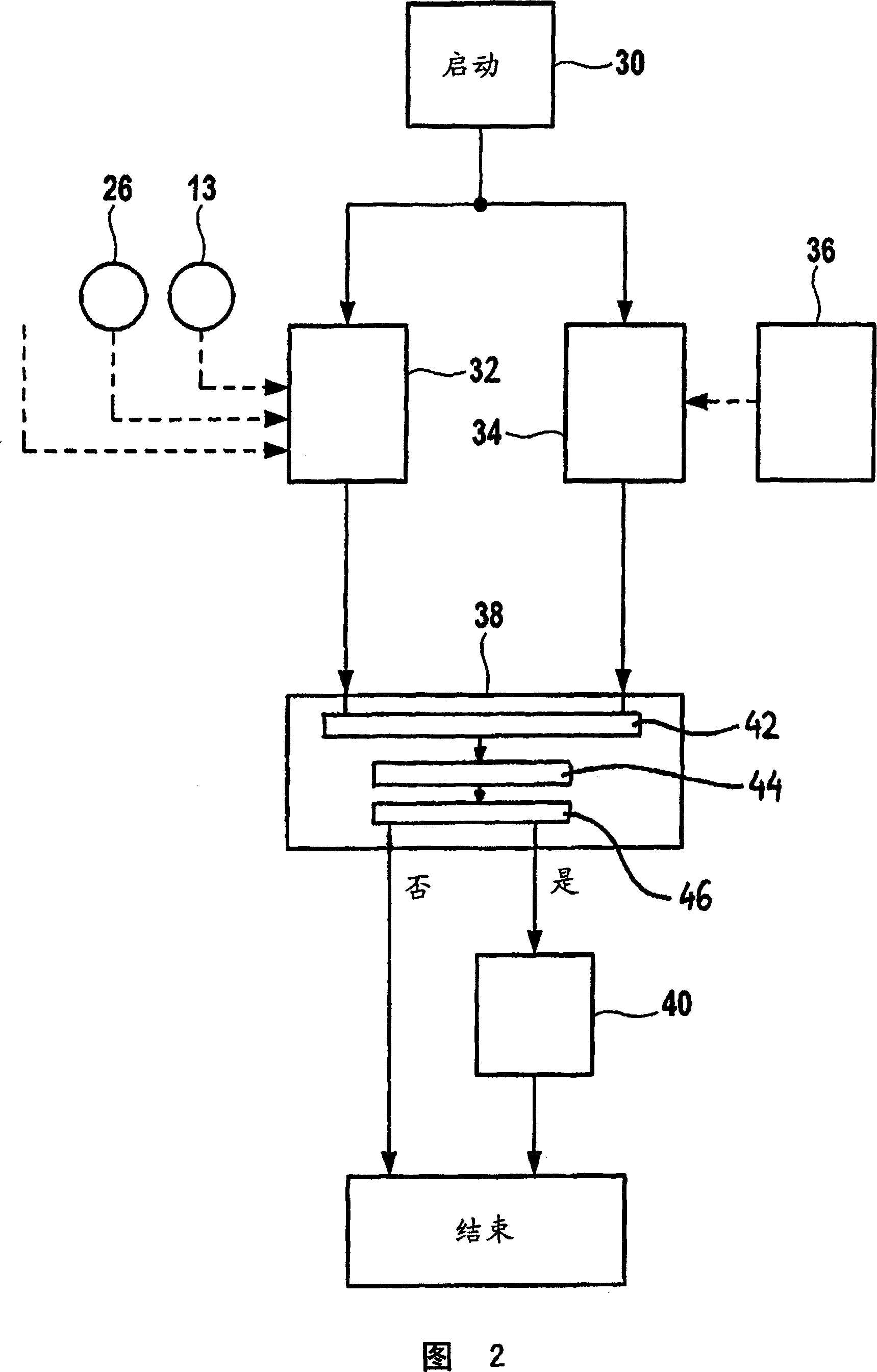
External adjustment steps applied beyond a controller to increase actual power relative to design power in a gas engine is known, such as using an additional apparatus. In order to recognize the external adjustment steps, offset between an actual power parameter (32) and a nominal power parameter (34) provided by the controller is proposed to be analysed and processed.

Description

technical field [0001] The invention relates to a method for identifying external adjustment measures by which the actual power of an internal combustion engine can be increased relative to the design power. Background technique [0002] Measures to increase the power of internal combustion engines in vehicles are increasingly being disseminated under the cue "chip tuning". The danger, however, is that, by means of this power increase, the design power of the internal combustion engine is exceeded in a range that causes damage to the internal combustion engine. Hence the question of guarantee or who is guaranteed against the damage incurred. [0003] In order to facilitate the analysis and the difficult evidentiary problems associated with this, methods are known on the market with which it is supposed to be possible to detect such impermissible adjustment measures. DE 10002203 A1, for example, describes a control system of an internal combustion engine that is protected a...

Claims


Application Information

Patent Timeline
Patent Type & Authority Applications(China)
IPC IPC(8): F02D41/22
CPCF02D41/22Y02T10/40F02D2041/1432F02D41/1497F02D2200/0602F02D41/2432
Inventor V·皮查尔W·格尔温C·库茨
Owner ROBERT BOSCH GMBH
Learn More