Supercharge Your Innovation With Domain-Expert AI Agents!

Switching device

A switch device and switch technology, applied to the power device, electric switch, circuit device and other directions inside the switch, can solve the problems of motor damage, motor receiving wrong operation instructions, etc., and achieve the effect of avoiding conflicts

Active Publication Date: 2007-02-28
SCHNEIDER ELECTRIC IND SAS
View PDF0 Cites 5 Cited by
  • Summary
  • Abstract
  • Description
  • Claims
  • Application Information

AI Technical Summary

Problems solved by technology

In manual mode, due to possible misoperation, the motor may still be powered and even receive wrong operation instructions, and manual operation may cause damage to the motor and other safety issues

Method used


Image

  • Switching device
  • Switching device
  • Switching device

Examples


Embodiment Construction

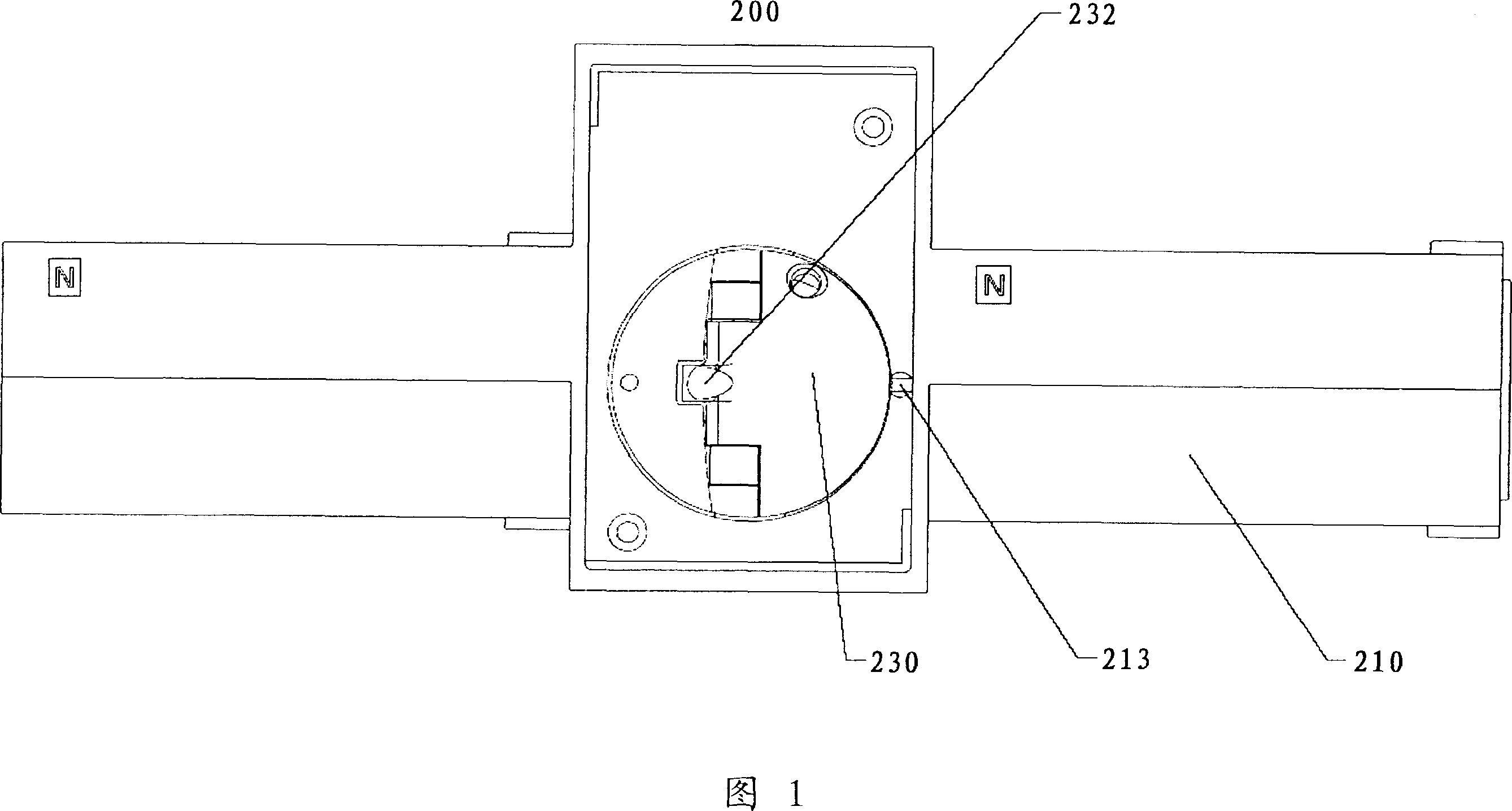
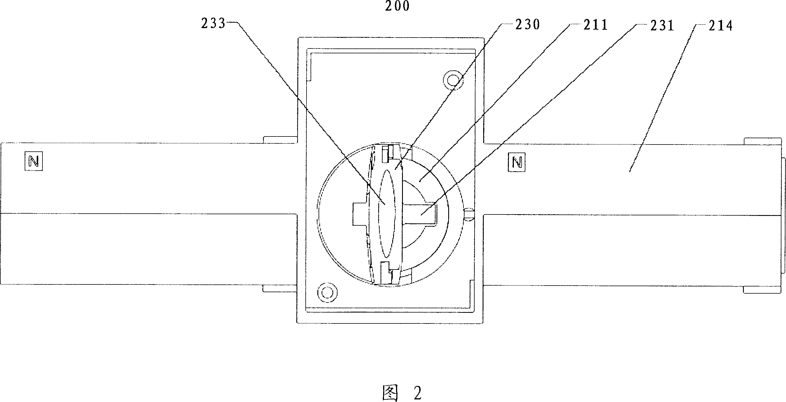
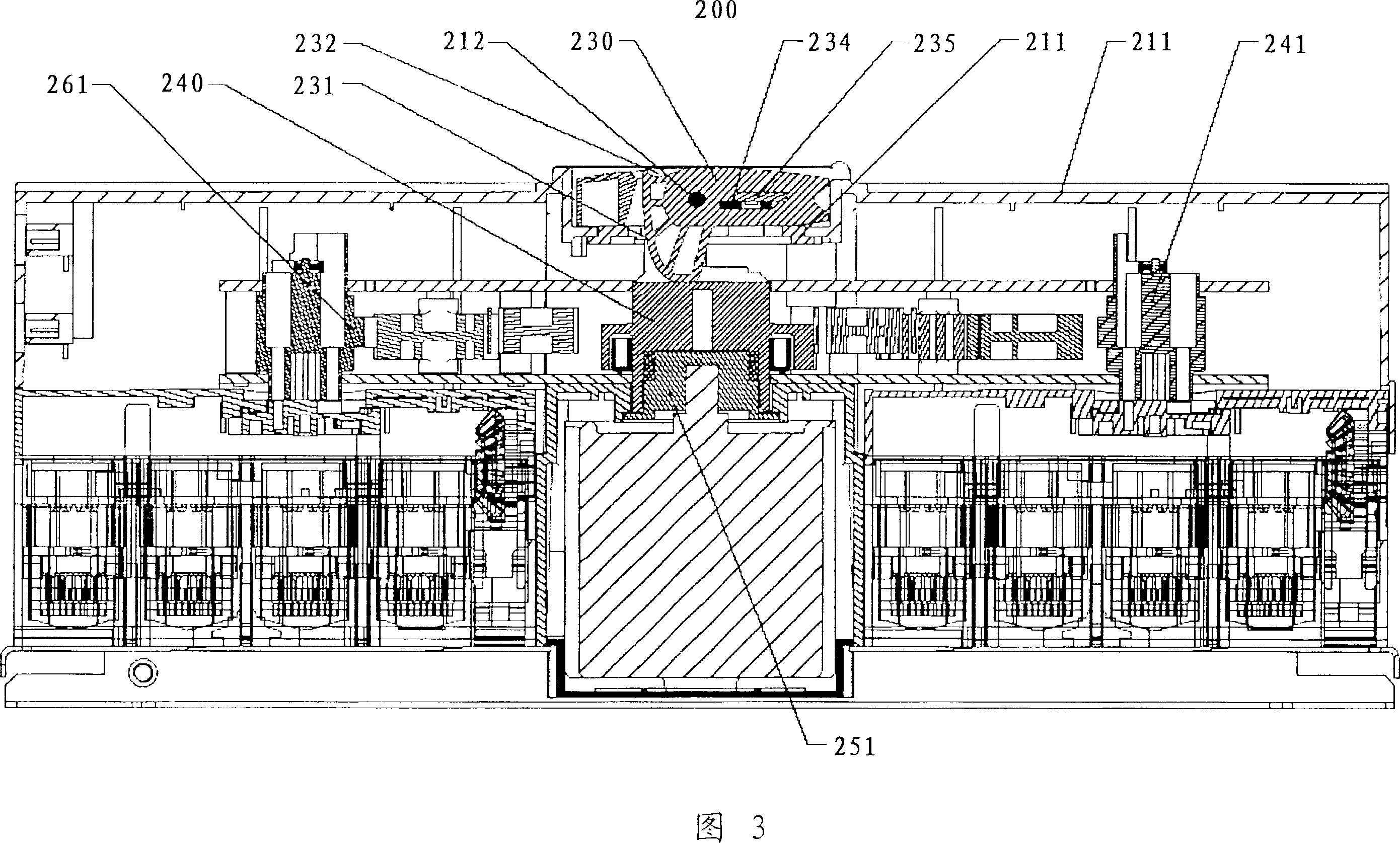
[0021] Referring to Figures 1 to 4, a switching device according to an embodiment of the present invention is shown. Figures 1 and 2 show top views of the switching device in automatic mode and manual mode, respectively. 3 and 4 show cross-sectional views along line A-A in FIGS. 1 and 2, respectively. Switch device 200 comprises, frame 21, has circular groove 211 on its operating surface; The operating handle 230 that is arranged in this groove; And transmission mechanism, it comprises the main gear 240 that is connected with handle 230, and motor (not shown Out) the clutch gear 250 connected, and the switch gear 260 connected with the main gear 240. The handle 230 can rotate around its center in the circular groove 260 , and a part of the handle 230 forms a cam 231 . The support shaft 212 is fixed on the frame 210 and passes through the handle 230 so that the handle 230 can rotate around the support shaft 212 .

[0022] Referring to FIG. 1 and FIG. 3 , in the automatic mod...


PUM


Abstract

The invention relates to a switch device, with frame, operation handle, and transmitter. Wherein, the frame has round groove at the operation surface; the operation handle is inside the groove; the operation handle can move the lower position relative to the automatic mode to the higher position relative to the hand-operated mode; the handle can rotate in the groove at two positions; the transmitter comprises main gear, clutch gear connected to the motor and the switch gear connected to the main gear; the main gear, clutch gear, and handle form clutch; therefore, in automatic mode, the main gear is meshed with clutch gear, and in hand-operated mode, the main gear is detached from the clutch gear, to avoid affecting motor when rotating the handle.

Description

technical field [0001] The invention relates to a switching device with two modes of operation, in particular a switching device for use in an ATSE (Automatic Transfer Switching Equipment). Background technique [0002] Switching devices are widely used in many fields, for example for power supply in emergency situations. In the event of a sudden power failure, switching devices are typically activated to divert the power line from the normal source to a backup source, such as an independent generator. Most switching devices work in two modes, automatic and manual, to complete the switching action. [0003] Referring to Figures 9 to 11, a conventional switching device used in an ATSE is shown. FIG. 9 is a top view of the conventional switch device in manual mode, and FIGS. 10 and 11 are schematic cross-sectional views of the conventional switch device in automatic mode and manual mode, respectively. The conventional switch device 1 has a frame 10 , a handle 11 , a clutch ...

Claims


Application Information

Patent Timeline
Patent Type & Authority Applications(China)
IPC IPC(8): H01H3/00H01H3/02H01H3/26
CPCH01H3/227H01H3/54H01H2300/018H02J9/06H01H2239/038H01H2239/032
Inventor 刘振忠萨旺特·普拉文比扎德·伯纳德
Owner SCHNEIDER ELECTRIC IND SAS
Features
  • R&D
  • Intellectual Property
  • Life Sciences
  • Materials
  • Tech Scout
  • Unparalleled Data Quality
  • Higher Quality Content
  • 60% Fewer Hallucinations
Learn More