Movable fence and method of opening/closing movable fence

A movable guardrail and door body technology, applied in door/window accessories, transportation and packaging, power control mechanism, etc., can solve the problems of passengers getting on and off the bus, achieve the effect of smooth getting on and off, easy monitoring, and lightening the burden

Inactive Publication Date: 2007-02-28
MITSUBISHI HEAVY IND LTD
View PDF1 Cites 22 Cited by
  • Summary
  • Abstract
  • Description
  • Claims
  • Application Information

AI Technical Summary

Benefits of technology

In this design described in this patented technology, there is a mobile gate system used during passenger loading and unloading operations. It consists mainly of a rail mounted above ground level, which allows cars to pass under them without hitting rails while they leave behind. A moving barrier called a door also moves back and forth across its way, creating space within the tunnel where vehicles may go upstairs or down stalls waiting for workers to enter. By controlling these movements, the gateway reduces pressure on stations staff and improves safety measures. Additionally, if one section needs more room due to increased traffic demand, multiple sections can be added instead of just having only one entrance area. Overall, this innovation helps improve efficiency and security levels in transport systems like airplanes.

Problems solved by technology

The technical problem addressed in this patents relates to improving safety measures against train accidents caused by passenger movement within specific areas called "railways," specifically during peak hours. Existing solutions involve adding extra parts like gates to improve security but they also increase weight and require space. Additionally, existing designs have issues related to reducing the number of components needed while still providing sufficient protection without increasing their overall dimensions.

Method used


Image

  • Movable fence and method of opening/closing movable fence
  • Movable fence and method of opening/closing movable fence
  • Movable fence and method of opening/closing movable fence

Examples


Embodiment Construction

[0102] Embodiments of the movable guardrail according to the present invention will now be described with reference to the accompanying drawings.

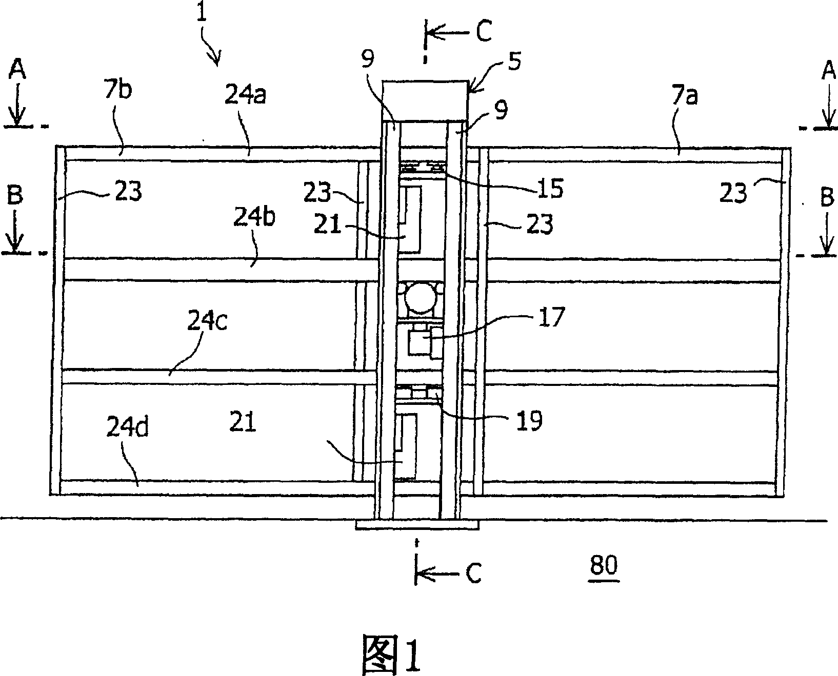
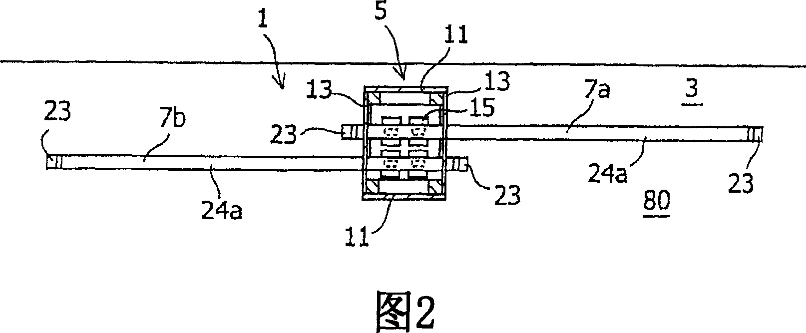
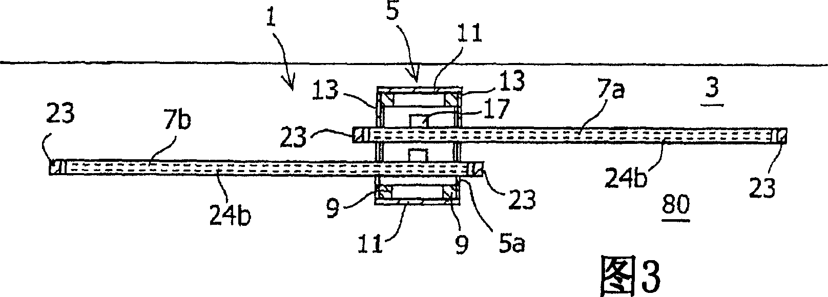
[0103] 1 is a front view of a platform door used as a movable guardrail according to the present invention, FIG. 2 is a sectional view along line A-A of FIG. 1 , FIG. 3 is a sectional view along line B-B of FIG. 1 , and FIG. A sectional view along line C-C of FIG. 1 . In this specification, the front and the rear refer to directions across the length direction of the platform 80 (i.e., the direction of travel of the train), the front is the platform 80 side, and the rear is the railway track side, and the right and left refer to the is the length direction of the platform 80, that is, the traveling direction of the train.

[0104] The platform door 1 is provided along the edge portion 3 on the railroad track side of the platform 80 and is supported by a door frame 5 erected on the platform 80 . The door frame 5 has upright column...


PUM


Abstract

The boarding-alighting port of a train having different door positions is made consistent with the open portion of a platform door according to the type of train to allow passengers to get on and off the train safely and smoothly. The platform door 1 includes a door pocket 5 provided in an end portion of a platform 80 so as to face to a train arriving at the platform 80, and door bodies 7a and 7b advancing and retreating through an opening of the door pocket 5. The opening through which the door bodies 7a and 7b advance and retreat is formed at both ends of the door pocket 5 in the advance/retreat direction of the door bodies 7a and 7b, the length in the advance/retreat direction of the door bodies 7a and 7b is made longer than the length of the door pocket 5 between both ends, and the platform door 1 is arranged so that the opening of the door body 7a, 7b is adjusted so as to correspond to the door opening of the train. The opening of the door body7a, 7b is controlled by a control unit according to the door arrangement information of the train arriving at the platform.

Description


Claims


Application Information

Patent Timeline
Owner MITSUBISHI HEAVY IND LTD
Why Eureka
Try Eureka