
Underwater glider floatage control device

An underwater glider and control device technology, which is applied to underwater ships, underwater operation equipment, motor vehicles, etc., can solve problems such as difficulty in deep-sea development, and achieve the effect of convenient maintenance.

Inactive Publication Date: 2007-03-07
ZHEJIANG UNIV
View PDF0 Cites 21 Cited by
  • Summary
  • Abstract
  • Description
  • Claims
  • Application Information

AI Technical Summary

Problems solved by technology

Limited by the power of the stepping motor and the performance conditions of the hydraulic cylinder, the working depth of the underwater glider is only tens of meters, and it is difficult to develop into the deep sea

Method used


Image

  • Underwater glider floatage control device
  • Underwater glider floatage control device

Examples


Embodiment Construction

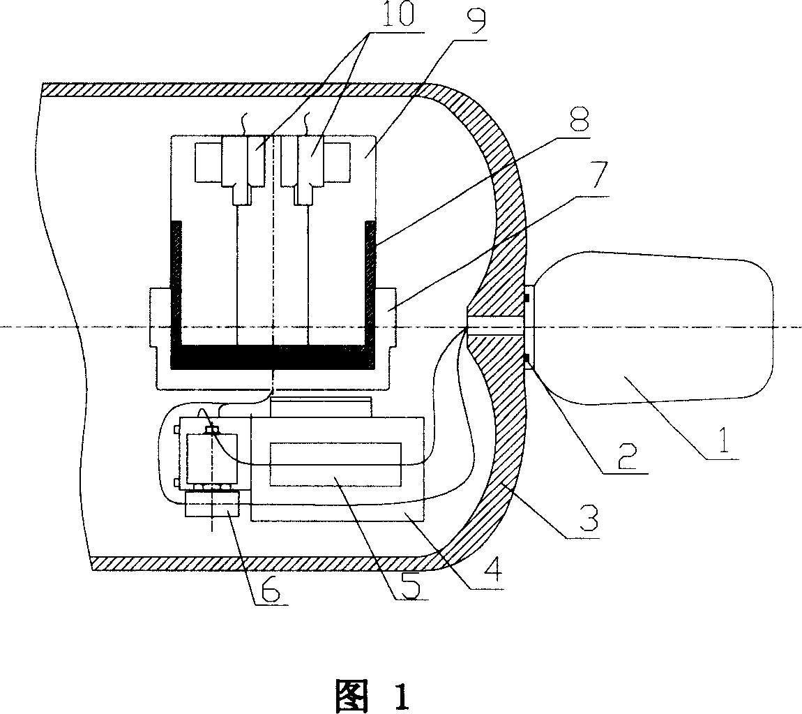
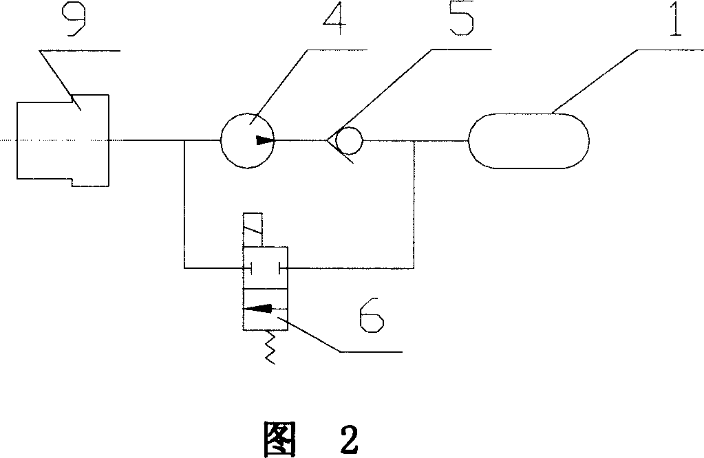
[0008] As shown in FIGS. 1 and 2 , the buoyancy control device of the underwater glider includes a small high-pressure pump 4 , a small solenoid valve 6 , a small one-way valve 5 , an oil chamber 9 and an oil bag 1 . Small high-pressure pump 4, small solenoid valve 6, small one-way valve 5 and oil cavity 9 are arranged inside pressure-bearing shell 3; oil bag 9 is arranged outside pressure-bearing casing 3, and the surface is in direct contact with seawater. The connection between the oil bag 1 and the pressure housing 3 is sealed with an o-ring 2 . The oil chamber 9 is composed of a chamber body 7 , a piston 8 and two linear potentiometers 10 . The oil chamber 9 and the oil bag form a circuit through a small high-pressure pump 4 and a small one-way valve 5, and are communicated through a small electromagnetic valve 6 at the same time. The function of the small one-way valve 5 is to prevent the oil in the circuit from flowing back to the oil chamber 9 through the small high-p...


PUM


Abstract

This invention relates to the buoyancy control device of an underwater glider. Most of the current underwater buoyancy control for gliders utilizes the alternative movement of the piston of the hydraulic cylinder anchored by the stepper motor, so as to control the inlet and charge of oil from the oil bag and therefore make it rather difficult to expand its application in deep sea. This invention comprises of those miniature high pressure pump, miniature electromagnetic valve, miniature single direction valve and oil cavity that located inside the pressure bearing housing, and also an oil bag that located outside of the pressure bearing housing. The oil recess comprises of a cavity, inside which a piston is equipped and linked with it closely for motion with two linear potentiometers on the piston. A loop is formed by the oil recess, miniature high pressure pump, miniature single direction valve, miniature electromagnetic valve and an oil bag. Without the interference of the inclining status of the body, it can control the change of the buoyancy force, so as to make the underwater glider sail along the planned route and therefore realize the progress of underwater glider's sailing toward the deep sea.

Description

technical field [0001] The invention relates to a control device, in particular to a buoyancy control device of an underwater glider that can be widely used in water body water quality monitoring, underwater resource survey and environmental monitoring. Background technique [0002] At present, most of the automatic detectors used for marine water quality monitoring, underwater resource surveying, and environmental monitoring research use propellers and other propulsion methods, so after working for a short time, they need to supplement power energy. Frequent charging procedures greatly limit the distance and depth of the probe in the ocean. For underwater gliders using buoyancy as a power source, most of the buoyancy control uses stepping motors to drive the piston in the hydraulic cylinder to reciprocate, so that the oil in the cylinder is sucked into or discharged from the oil bag. Limited by the power of the stepping motor and the performance conditions of the hydraulic...

Claims


Application Information

Patent Timeline
IPC IPC(8): B63G8/24B63C11/00
Inventor 杨灿军赵伟诸敏陈鹰
Owner ZHEJIANG UNIV
Learn More