
Three-dimensional harmonic wave gear with involute tooth outline

A three-maintenance, harmonic drive technology, used in gear transmissions, transmissions, components with teeth, etc., can solve the problem of reducing the amplitude of the change of the involute tooth profile of the flex wheel, and cannot be applied to various situations. not mentioned etc.

Active Publication Date: 2007-03-07
BEIJING CTKM HARMONIC DRIVE CO LTD
View PDF7 Cites 26 Cited by
  • Summary
  • Abstract
  • Description
  • Claims
  • Application Information

AI Technical Summary

Problems solved by technology

[0015] 1. The patent only mentioned that the variation coefficient of the flexspline involute tooth profile should be changed along the length direction of the teeth, but it did not mention that the tooth height of the two gears or one of them should be adjusted along the length direction of the teeth at the same time. change to avoid interference
[0016] 2. This patent only allows the variation coefficient of the flexspline involute tooth profile to change along the length direction of the tooth, and does not mention that the variation coefficient of the rigid spline involute tooth profile can also be appropriately changed along the length direction of the tooth if necessary , in order to reduce the change range of the variation coefficient of the flexspline involute tooth profile, and avoid the excessive change range of the variation coefficient of the flexspline involute tooth profile from affecting the strength of the flexspline. The variation coefficient of the open tooth profile remains unchanged, and only the variation coefficient of the involute tooth profile of the rigid wheel changes along the length direction of the tooth
[0017] 3. A variety of cams with different profiles can be used in the harmonic transmission device, such as elliptical cams, cosine cams, two-force cams, four-force cams, etc. This patent does not analyze the influence of cams with different profiles on the calculation formula
In fact, for cams with different profiles, the formulas for calculating the tooth profiles of flexsplines and rigid splines are different. The formula for calculating the displacement coefficient of flexsplines proposed in this patent cannot be applied to many situations.
[0018] 4. The patent restricts the rigid spline and the flex spline to take the same original tooth profile angle. It does not mention that the original tooth profile angle of the flex spline and rigid spline can also be based on the requirements for meshing clearance. take a different value

Method used


Image

  • Three-dimensional harmonic wave gear with involute tooth outline
  • Three-dimensional harmonic wave gear with involute tooth outline
  • Three-dimensional harmonic wave gear with involute tooth outline

Examples


Embodiment Construction

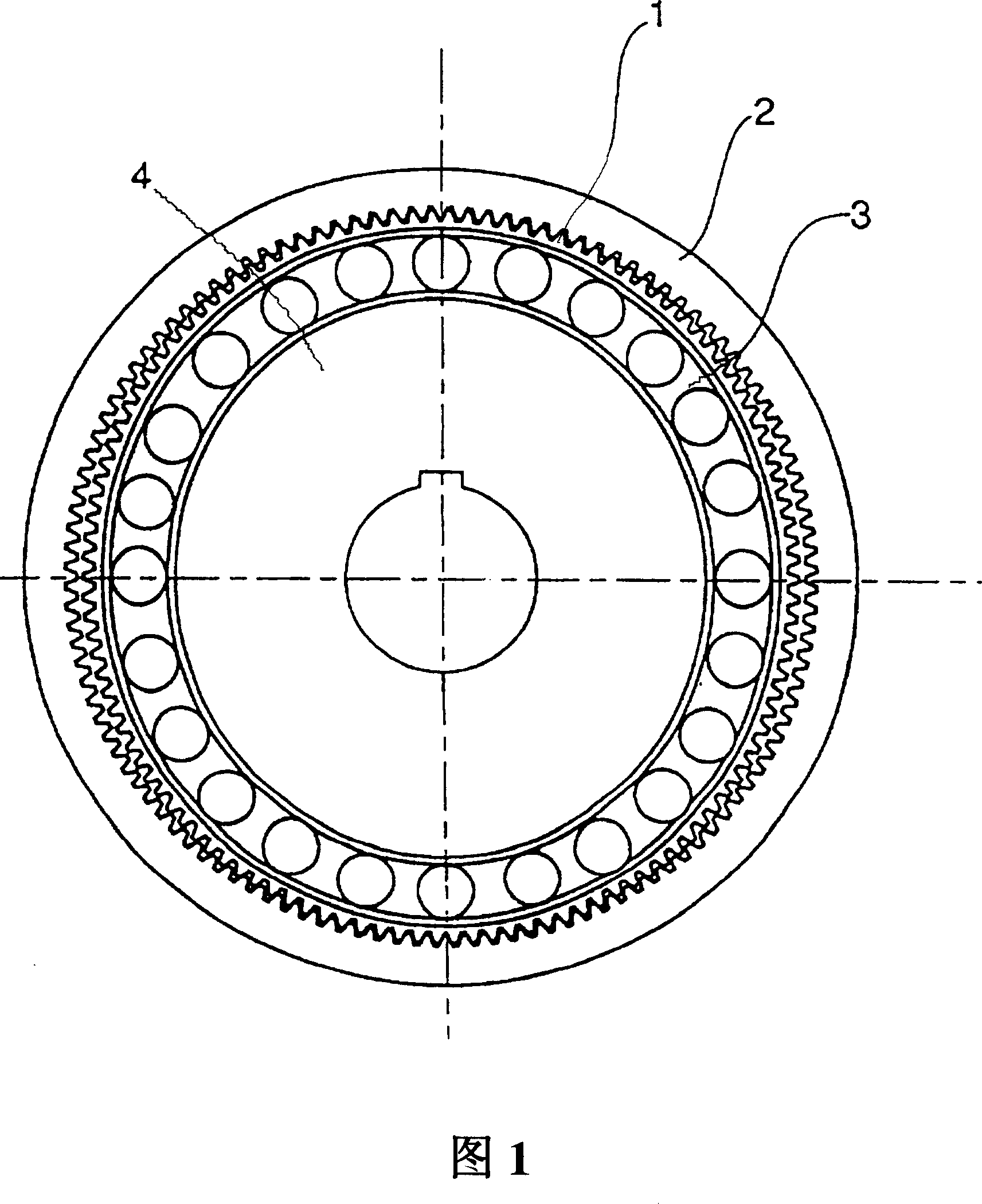
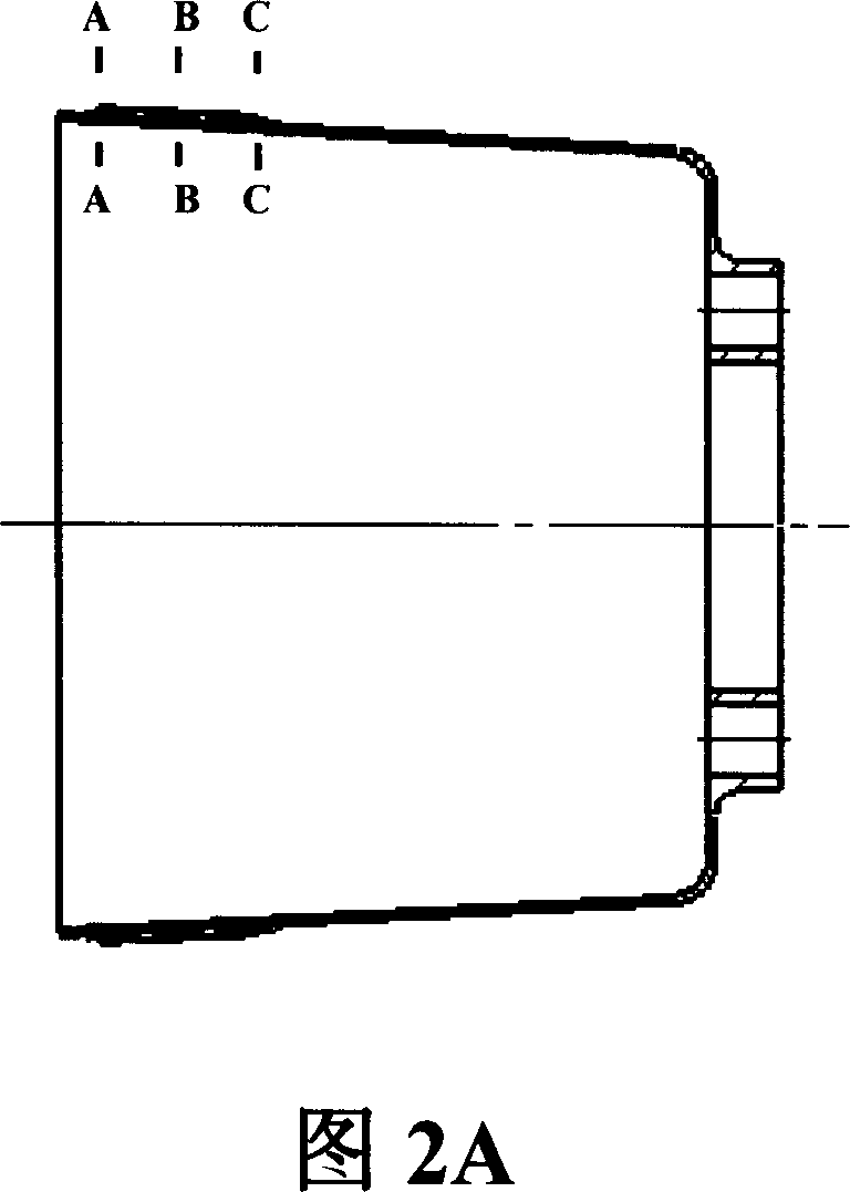
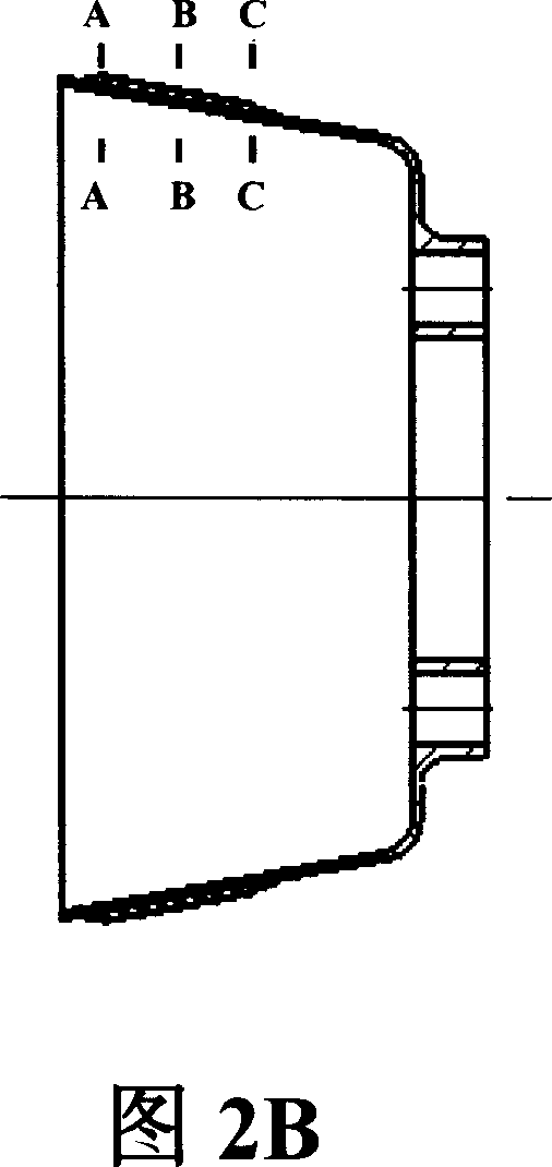
[0045] The invention adopts the method of directly calculating the clearance between each pair of teeth of the flexible spline and the rigid spline to design and calculate the tooth profile of the flexible spline and the rigid spline under no-load conditions. This method is not only applicable to the case when the flexible spline and the rigid spline adopt the involute tooth profile, but also applies to the case when the flexible spline and the rigid spline adopt the non-involute tooth profile, and is applicable to any kind of cam profile Condition. The following is a brief description of this design calculation method by taking the involute tooth profile of the flexible spline and the rigid spline as an example.

[0046] Follow the following two principles in the design.

[0047] 1. The neutral layer of the flexible spline does not elongate or shorten after deformation;

[0048] 2. The shape of the tooth profile remains unchanged after the flexspline is deformed, and the sy...


PUM


Abstract

This invention discloses one involute gear three-dimensional resonance drive device, which adopts design and process technique as flexible wheel and rigid wheel outline and is characterized by the following: at flexible wheel length taking gear vertical to flexible whell axis section; according to each section different radium deformation parameters designs the outline between flexible and rigid wheels to get the involute outline with variable parameters.

Description

technical field [0001] The invention relates to a mechanical transmission device, in particular to a harmonic transmission device using a flexible spline and a rigid spline with an involute tooth profile. Background technique [0002] The harmonic drive reducer is a new type of transmission device invented by C.W.Musser in the 1950s (see US Patent 2906143). It has a wave generator with a cam and a flexible bearing in the inner hole of the flexible spline with external teeth. The cam profile is an ellipse or other nearly elliptical curve. The profile curve of the cam can be expressed in polar coordinates, and the line connecting the two points with the largest radial direction symmetrical to the center of the cam is called the major axis of the cam. The wave generator is installed on the open end of the flexible spline (that is, the end away from the bottom of the flexible spline), and the open end is supported by the wave generator into an ellipse or other nearly elliptical ...

Claims


Application Information

Patent Timeline
IPC IPC(8): F16H1/24
CPCF16H55/0833
Inventor 李克美尹仪方陈仕贤
Owner BEIJING CTKM HARMONIC DRIVE CO LTD
Learn More