Manufacturing method of electro-moulding pipe and electro-moulding pipe, thin wire used for manufacturing same

A manufacturing method and electroforming technology, applied in electroforming, electrolysis process, etc., can solve the problem that it is not so easy to remove thin wires

Active Publication Date: 2007-03-07
LUZCOM
View PDF1 Cites 6 Cited by
  • Summary
  • Abstract
  • Description
  • Claims
  • Application Information

AI Technical Summary

Problems solved by technology

[0009] However, removal of thin wires from electrodeposited (precipitated) metals i

Method used


Image

  • Manufacturing method of electro-moulding pipe and electro-moulding pipe, thin wire used for manufacturing same
  • Manufacturing method of electro-moulding pipe and electro-moulding pipe, thin wire used for manufacturing same
  • Manufacturing method of electro-moulding pipe and electro-moulding pipe, thin wire used for manufacturing same

Examples


Embodiment Construction

[0101] Embodiments of the present invention will be described in more detail with reference to the drawings.

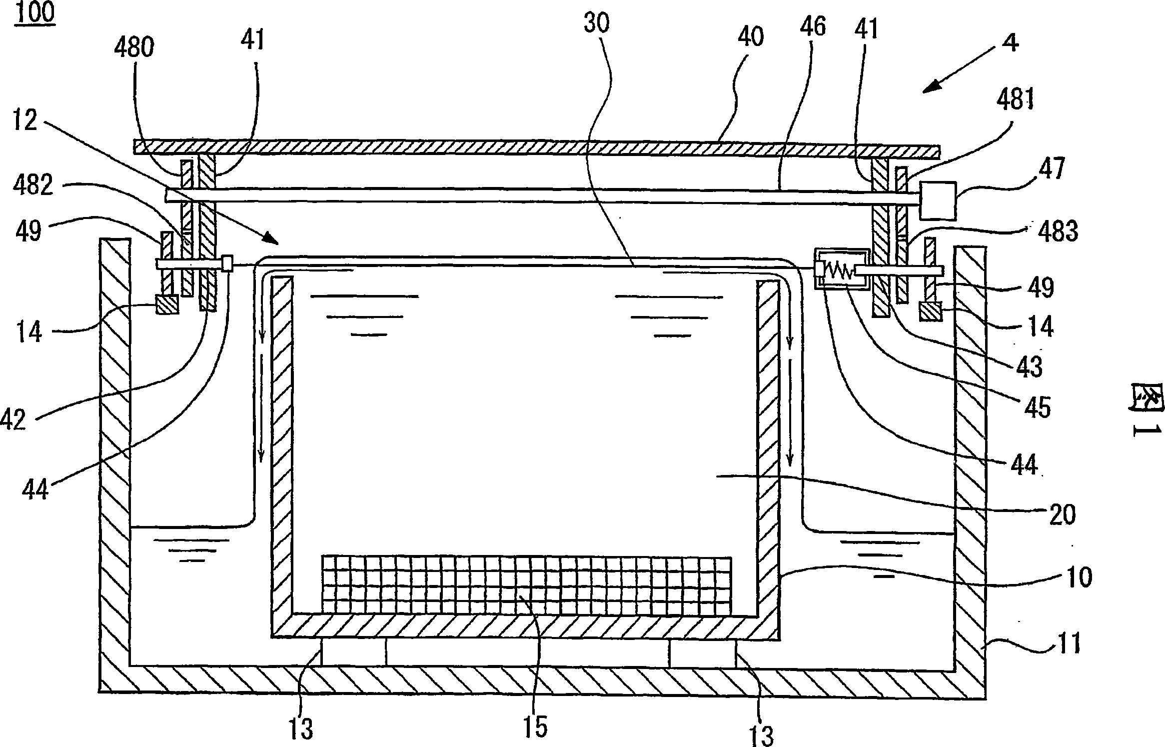
[0102] FIG. 1 is a cross-sectional explanatory view showing an example of an electroforming apparatus for producing an electroformed tube of the present invention.

[0103] First, an electroforming apparatus for manufacturing an electroformed tube will be described.

[0104] The electroforming apparatus 100 includes an electroforming tank 10 and an outer tank 11 that accommodates the electroforming tank 10 inside. The upper openings of the electroforming tank 10 and the outer tank 11 always supply an electrolytic solution (electroforming solution) 20 into the electroforming tank 10 during operation. In this way, the electrolytic solution 20 overflows from the upper part of the electroforming tank 10 and flows into the outer tank 11 . In this embodiment, as the electrolytic solution 20, for example, an electrolytic solution obtained by adding a glazing agent and a bi...


PUM


Abstract

The invention provides a method of producing an electrocast tube having a fine inner diameter, and an electrocast tube. It also provides a thin wire material for production of an electrocast tube having a fine inner diameter. An electrocast tube producing method comprising the steps of forming an electrodeposit around a thin wire material (30) by electrocasting, and removing the thin wire material (30) from the electrodeposit, wherein the thin wire material (30) is removed either by heating the electrodeposit for thermal expansion or by cooling the thin wire material (30) for contraction, so as to form a clearance between the electrodeposit and the thin wire material (30), followed by gripping and pulling, or sucking the thin wire material (30) or physically pushing it away or blowing gas or liquid to push it away.

Description

technical field [0001] The present invention relates to a method of manufacturing an electroformed (this specification is referred to as "electroformed") tube, an electroformed tube, a thin wire material for producing an electroformed tube, and more particularly, to a method of manufacturing an electroformed tube having a small inner diameter and electroformed tubes. In addition, it relates to a fine wire used for manufacturing an electroformed tube having a small inner diameter. Background technique [0002] Conventionally, when an integrated circuit such as an LSI is manufactured, a semiconductor pattern is completed according to a design, and an inspection is performed to see if the electrical continuity is good. In this inspection, a device including a plurality of contact probes (referred to as a "probe device" in this specification) is used, and the needles of the contact probes are brought into contact with each formed electrode. The contact probe has a structure in...

Claims


Application Information

Patent Timeline
IPC IPC(8): C25D1/02C25D1/20
CPCC25D1/02
Inventor 小田德治市川裕
Owner LUZCOM
Why Eureka
Try Eureka